


Commander Installation Guide
Page 70 of 81 Trilogy Communications Limited
Issue 9
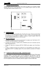
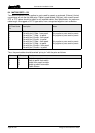
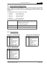
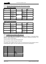
Audio I/O – D15 Fixed Socket
Pin Function Notes
1 Slave Mic Input Line level, un-balanced
2 +15V Out (for slave mic panel) NOT protected!
3 Clean Mic Out + Line level, balanced, pair with 11
4 Ext CUT Input (for slave mic panel) Parallel function to front panel Cut
Switch. Ground to activate
5 Chassis Ground
6 No connection
7 External Input to LS Amp - Line level, balanced, pair with 14
8 Matrix Audio Input to Panel / parallel output - Line level, balanced, pair with 15
9 Ext Mic Cut output (to slave panel) Normally grounded. O/P is open
circuit when front panel cut selected.
10 -15V Out (for Slave mic panel) NOT protected
11 Clean Mic Out - Line level, balanced, pair with 3
12 Mic Ground
13 Loudspeaker Output 8 ohm loudspeaker
14 External Input to LS Amp + Line level, balanced, pair with 7
15 Matrix Audio Input to Panel / parallel output + Line level, balanced, pair with 8
NB 15V supplies are also used to derive 12V for panel. (Thermally Fused @ 0.7A)
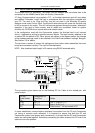
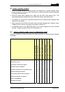
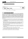
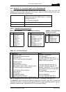
8.5.3 500-30 SERIES DIP SWITCH SETTINGS
Within the panel a series of DIP switches determine the correct panel type. These are
factory set and are included for reference in section 10.1
A further set of DIP swit
ches is user accessible at the top side of the panel and control the
action of the front panel CUT switch. The factory default is shown in the table below.
Cut Switch Action DIP 1 DIP 2 DIP 3
No action OFF OFF OFF
Changeover to HSet MIC (default) ON OFF OFF
LS cut OFF ON OFF
Changeover to HSet MIC and LS cut ON ON OFF
MIC cut OFF OFF ON
Changeover to HSet MIC and MIC cut ON OFF ON
LS cut and MIC cut OFF ON ON
Everything ON ON ON