


Commander Installation Guide
Page 18 of 81
Issue 9
Trilogy Communications Limited
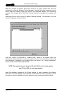
If this phase is successful and the TDM controller is running correctly, switch off the system.
Turn the flash bank selector switch to an active bank (i.e 1,2,3 or 4) and re-start the system.
The yellow polling LED on the 500-02 Talkback Controller will start to flash, indicating that a
configuration has been loaded from the Flash RAM and is active on the system.
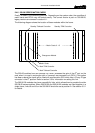
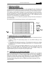
Finally, the standby Talkback and TDM controllers may be added. Switch the system off,
carefully add the cards in the positions shown in section 2.4.6 then re-power the system. The
main TDM c
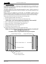
ontroller (on the left side of the frame) should now initialise and display an LED
pattern as on the previous page. The Standby TDM controller (on the right side of the frame)
should display the “standby” pattern which is LED 1-8 alternating with LED 9-16.