


Commander Installation Guide
Trilogy Communications Limited Page 47 of 81
Issue 9
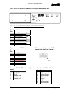
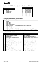
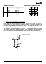
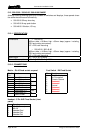
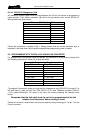
GPIO (Local logic in and out) - D9 Fixed Socket
Pin Function Notes
1 Ground
2 Logic Input 1
3 Logic Input 2
4 Logic 2 Out Common
5 Internal +5V (Out) Protected with 0.5A thermal fuse & 1N4002 diode.
6 Logic Output 1
7 Logic 1 Out Common
8 Logic Output 2
9 Logic Input +VCC NB Pin 9 may be driven by external voltage (With dropper
resistor if greater than 5V), or by internal +5V via pin 5.
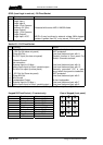
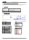
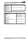
Audio I/O – D15 Fixed Socket
Pin Function Notes
1 No connection
2 +12V Out Fused internally 0.5A
3 Clean Mic Out + Line level, balanced, pair with 11 –
o/p is affected by CUT switch
4 Ext CUT Input Parallel function to front panel Cut
Switch. Ground to activate
5 Chassis Ground
6 No connection
7 External Input to LS Amp - Line level, balanced, pair with 14
8 Matrix Audio Input to Panel / parallel output - Line level, balanced, pair with 15
9 No connection
10 No connection
11 Clean Mic Out - Line level, balanced, pair with 3
12 Internal Ground
13 No connection
14 External Input to LS Amp + Line level, balanced, pair with 7
15 Matrix Audio Input to Panel / parallel output + Line level, balanced, pair with 8