


Commander Installation Guide
Issue 9 Trilogy Communications Limited Page 5 of 81
5. CONTROL PANELS .......................................................................................... 35
5.1 I
NTRODUCTION ............................................................................................................ 35
5.2 C
URRENT RANGE ......................................................................................................... 35
5.3 C
ONTROL PANEL FACILITY COMPARISON TABLE ........................................................... 36
5.4 500-41-
XX SERIES DESKTOP PANELS ........................................................................... 37
5.5 500-31-51
16 KEY PLUS DIAL PAD CONTROL PANEL ....................................................... 38
5.5.1 Specification ........................................................................................................ 38
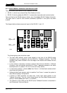
5.5.2 500-3x-5x S
eries Standard Control Panel Rear View ......................................... 39
5.5.3 500-3x-5x S
eries Control Panel Connections ..................................................... 39
5.5.4 500-3x-5x S
eries DIP Switch Settings ................................................................ 41
5.6 500-43-50
12 WAY ROTARY ENCODER EXPANSION PANEL ............................................ 42
5.6.1 Specification ........................................................................................................ 42
5.6.2 Rear Conne
ctor Layout ....................................................................................... 42
5.7 500-42-50
1U, 10 LEVER KEY PANEL WITH LED DISPLAYS. ............................................ 43
5.7.1 Specification ........................................................................................................ 43
5.7.2 Rear Conne
cor Layout ........................................................................................ 43
5.7.3 Connections ........................................................................................................ 43
5.8 C
ONTROL PANEL GPIO EXTERNAL CIRCUITRY.............................................................. 45
5.9 500-31-60
STANDARD FACILITY 16 KEY CONTROL PANEL .............................................. 46
5.9.1 Specification ........................................................................................................ 46
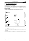
5.9.2 Rear Panel Layout
.............................................................................................. 46
5.10500-33-00
/ 500-45-00 / 500-46-00 RANGE ................................................................. 48
5.10.1Specification ........................................................................................................ 48
5.10.2Connections ........................................................................................................ 48
6. COMMANDER PROGRAMMING KIT ............................................................... 51
6.1 I
NTRODUCTION ............................................................................................................ 51
6.2 TT
PROG SOFTWARE .................................................................................................... 51
6.2.1 Set-up Routine .................................................................................................... 51
6.2.2 Starting the progra
mme ...................................................................................... 52
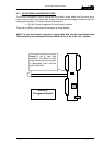
6.2.3 Connecting the
Hardware ................................................................................... 53
6.2.4 Co
mpleting the reprogram sequence .................................................................. 53
6.3 P
ROGRAMMING WITH THE 500-16-03 DOWNLOAD CONVERTER ..................................... 54
7. OTHER EQUIPMENT ........................................................................................ 55
7.1 B
ELTPACKS ................................................................................................................. 55
7.2 T
ELEPHONE INTERFACES ............................................................................................. 56
7.2.1 Telos ONE alignment .......................................................................................... 57
7.3 RT
EQUIPMENT ............................................................................................................ 58
7.4 500-22-00
ICIS-1 ISDN INTERFACE ............................................................................. 58
7.4.1 500-22-00 ICIS-1 ISDN Interface Connector Pin-Outs ....................................... 58
7.5 500-23-00
ICIS-2 ISDN INTERFACE ............................................................................. 60