


Commander Installation Guide
Page 54 of 81 Trilogy Communications Limited
Issue 9
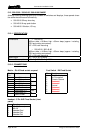
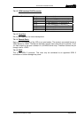
6.2.4.4 500-08-10 Changeover Card
An additional adaptor cable must be fitted between the D9 on the mauve re-programming
cable and the 10 pin Molex connector (J6) that is the connection point on the 500-08-10.
Wiring details are given below.
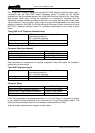
10 way IDT Header (500-08-10) D9 Free socket
1 1
2 6
3 2
4 7
5 3
6 8
7 4
8 9
9 5
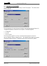
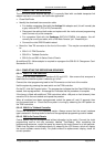
Follow the instructions in section 6.2.4.1. Always ensure that the correct hardware type is
selected
in the drop down list box and the appropriate programming code is loaded.
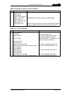
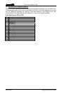
6.3 PROGRAMMING WITH THE 500-16-03 DOWNLOAD
CONVERTER
For programming Commander cards and panels, the connector is 9 way male to female with
the following connections. Note, not all pins are wired.
Commander Programming Cable
9 way D Male 9 way D Female
1 – Not used 1 – Not used
2 2
3 3
4 5
5 4
6 – Not used 6 – Not used
7 – Not used 7 – Not used
8 9
9 8
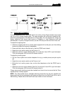
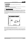
To program Commander cards you must set the changeover card (500-08-10) jumper J7 to
left and issue a reset on both the TDM (500-01-10/11) and Talkback controller (500-02-
11/12) cards beforehand. For cards in the rack, this means pressing the relevant reset
button.
Remember that the link cable from the unit to be programmed to the link
adapter must be present before issuing a reset.
Panels do not have a reset button and must be reset by briefly shorting pin 3 to pin 7 on the
9 way connector.