


Commander Installation Guide
Issue 9 Trilogy Communications Limited Page 29 of 81
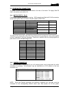
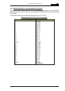
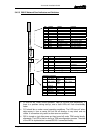
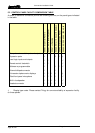
3.4.5.3 500-25 Network Card Indicators and Switches
Reset
8 way DIP Switch
1
|
|
|
|
8
1
|
|
|
|
|
|
|
|
|
13
LED Legend Activity Function
D8 +5V On +5V
D1 1 1Hz DSP 1 OK
D2 2 2Hz DSP 2 OK
D6 RESET Off Reset
D3 NO E1 CLK Off if net available No E1 Clock
D9 TDM D Off when started TDM Disabled
D10 1 DIS Off when started DSP Disabled (TDM)
D11 BUSY Quick flash TDM Busy
D12 COM1 Quick flash DSP Comms (TDM)
D13 E1 DIS Off if data available E1 Disabled
D14 2 DIS On when E1 down NET DSP Disabled
D15 BUSY On when buffers full NET DSP Busy
D16 COM2 Unused NET DSP Comms
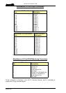
LED Legend Activity Function
D17 1 1Hz DSP 1 & 2 sync’d
D18 2 On when full IN Buffer full
D19 3 On when full OUT Buffer full
D20 4 On during start then off E1 clk & event off
command
D21 5 On Possible RX Data loss
D22 6 On if clk missing E1 Clock off
D23 7 Normally toggles Receiving H IP Data
D24 8 Normally toggles Transmitting H IP Data
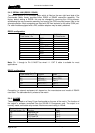
DIP Switch Functions
Sw Function Default Note
1 Cable Match OFF=
CAT 5
ON = Co-ax
2 Cable Length ON =
norm
OFF = “long”
3 undefined
4 undefined
5 undefined
6 UART IN OFF
7 UART OUT OFF
8 ERR CORR OFF
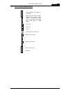
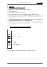
• D1 and D2 will, under normal operation, flash at 1Hz and 2Hz respectively. If
there is a problem during start-up, one or both LEDs will flash considerably
faster.
• D13 should be on under normal operating conditions. The LED turns off when
data comes in from a remote link but the off duration is very short and not
visible. It is therefore only useful to show an error condition.
• D20 is turned on just after power-up then turned off under TDM control shortly
afterwards. The LED is also on during a TDM reconfiguration process. The state
of the LED is duplicated on a remote 500-25 if connected directly.