


Commander Installation Guide
Issue 9 Trilogy Communications Limited Page 23 of 81
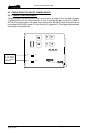
3.4 OTHER MATRIX CONNECTIONS
A number of other connections are provided on the rear of the matrix. For legacy Sub D9
matrix connectors, see section 8.4.
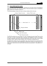
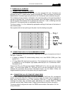
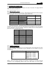
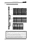
3.4.1 MATRIX PORTS – RJ-45
Commander systems delivered from spring - 2003 onwards are fitted with RJ-45 connectors
for the matrix ports. Rear connector unit part number is 500-07-50.
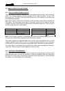
RJ-45 Pin Function Cable
1 Panel Data out + Matrix Data In Pair 1
2 Panel Data out -
3 Panel Data In + Matrix Data Out Pair 2
6 Panel Data In -
5 Panel Audio out + Matrix Audio In Pair 3
4 Panel Audio out -
7 Panel Audio in + Matrix Audio Out Pair 4
8 Panel Audio in -
shell Cable Screen
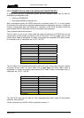
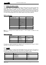
The 500-07-50 is fitted with a Sub D25 Fixed Socket which provides the 4-wire audio signals
for the 6 channels of that rear connector. These are in parallel with the existing signals on
pairs 3 and 4 of the corresponding RJ-45.
Input PIN + (HOT) PIN - (COLD)
1 24 12
2 22 10
3 20 8
4 18 6
5 16 4
6 14 2
Output PIN + (HOT) PIN - (COLD)
1 25 13
2 23 11
3 21 9
4 19 7
5 17 5
6 15 3
Ground 1
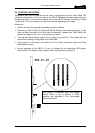
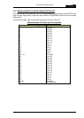
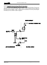
3.4.2 CAMERA CONNECTOR
This option provides a mixing pad for up to 6 camera inputs, and a single feed for audio
connection to cameras. The connector may be identified as a D15 socket on the rear
connector unit.
Matrix Sub-D15 Fixed Socket Pin (+,-) Description
8,15 Camera 1 input +,- to matrix
7,14 Camera 2 input +,- to matrix
6,13 Camera 3 input +,- to matrix
5,12 Camera 4 input +,- to matrix
4,11 Camera 5 input +,- to matrix
3,10 Camera 6 input +,- to matrix
1 Ground
2,9 Cameras Output +,- from matrix
NOTE: Since the Camera connector unit performs a passive mix, the gain must be
increased on the corresponding 500-06 matrix card. See section 3.5 of this guide.