


Commander Installation Guide
Trilogy Communications Limited Page 59 of 81
Issue 9
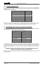
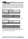
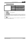
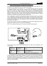
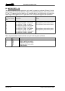
7.4.1.2 ISDN Interface RJ45 Connector
RJ45 Fixed Socket Pin 1 Not connected
Pin 2 Not connected
Pin 3 Tx to network A/Rx from terminal A
Pin 4 Rx from network A/Tx to terminal A
Pin 5 Rx from network B/Tx terminal B
Pin 6 Tx to network B/Rx from terminal B
Pin 7 Not connected
Pin 8 Not connected
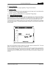
7.4.1.3 Com Port
D9, not yet supported, for future development.
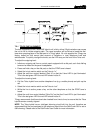
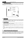
7.4.1.4 Remote Ports
Each input is the cathode of the LED on an opto-isolator. The anode is connected through a
470R resistor to +5VDC. Therefore to activate a control input, short the pin to ground, i.e. pin
10. Each output is the open collector of a ULN2003 driver chip. Therefore connect the pin
through load to +5VDC.
7.4.1.5 RJ45
This is the ISDN 2 connector. This must only be connected to an approved ISDN 2
connection or serious damage may occur.