


Commander Installation Guide
Page 80 of 81
Trilogy Communications Limited Issue 9
10.3 500-31-60 – PROGRAMMING CUT SWITCH OPERATION
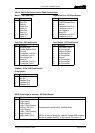
The cut switch operation is set by via the assign mechanism: press the assign switch,
depress any key, turn the Rotary Encoder (REN) until CutSw is displayed and then press
the same key again.
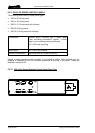
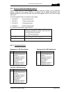
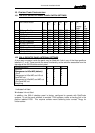
The LCD will display as follows, with the on/off labels above the switches 5, 6 and 7
respectively.
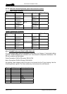
HSMic LSCut MCCut
On On Off
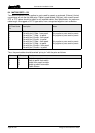
Name Function when Off Function when On
HSMic The headset microphone is not selected,
panel microphone is always used
The headset microphone is selected
instead of the panel microphone when
the cut switch is used
LSCut The panel loudspeaker is always active The panel loudspeaker is muted when
the cut switch is pressed
MCCut The panel microphone is always active The panel microphone is muted when
the cut switch is pressed
To change the setting press the associated key below (5, 6 or 7) to toggle the current state.
Note the settings are preserved during power down.
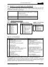
10.3.1 TEST FUNCTION
If switches 5 and 7 are up and switch 6 down when the unit is powered up, the unit will enter
test mode. Note in this mode the panel will no longer operate as a normal panel and must be
re-powered to do so. When connected to a matrix system, the test mode can also be entered
via the assign switch: press the assign switch, depress any key, rotate the REN until Test is
displayed and then press the same key again.
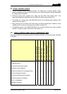
In test mode, the following features are available:
• When cut switch is up:
o Adjusting the REN will light each of the LEDs in turn
o Pressing each switch down will highlight the block of LCD characters
associated with that switch
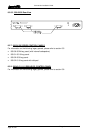
• When cut switch is down:
o Cut switch LED will light.
o Pressing each switch up/down will light associated red/yellow led.
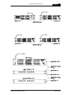
o Pressing each switch down will display text “12345” on LCD next to switch.
o Pressing assign/shift will fire GPO1/GPO2 respectively.
o Closing footswitch and logic 1 or 2 will report messages on LCD switch
positions 1, 2, and 3. Note these messages can get jumbled with LCD test
messages. The display will read: F1 x L1 x L2 x. where x is either ‘O’ or ‘C’
(open or closed).