


Commander Installation Guide
Page 58 of 81 Trilogy Communications Limited
Issue 9
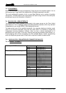
7.3 RT EQUIPMENT
Radio Talkback equipment may be supplied by Trilogy as part of a complete system. It is not
manufactured by Trilogy and will be supplied with the original equipment manuals.
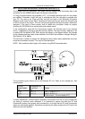
The usual configuration consists of one or more Base Stations and a number of portable
transceivers. The Base Stations are connected to the matrix using normal 4 wire audio ports
according to the pin-out information in Section 2.
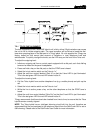
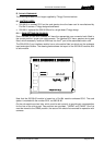
7.4 500-22-00 ICIS-1 ISDN INTERFACE
The 500-22 ICIS-1 ISDN interface is connected in the same manner as the Telos Hybrid
(see Section 0). The 1U package contains two 64k-bandwidth channels, which may be used
independent
ly or as a single ISDN2 (128k) bandwidth channel.
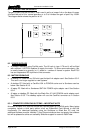
To make correct use of the available bandwidth, two separate telephone interface cards
(500-19-10) should be allocated, along with two matrix ports. It is possible to request two
independent incoming telephone numbers, either via your in-house switchboard of (if
appropriate) from your telco. In this way, incoming calls can be directed to either Bearer 1 or
2 and outgoing calls will be connected to the first available Bearer. Careful programming
within the telephone groups area of PathFinder is required to obtain the best results.
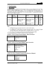
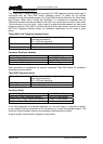
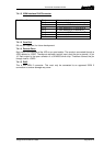
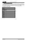
7.4.1 500-22-00 ICIS-1 ISDN INTERFACE CONNECTOR PIN-OUTS
7.4.1.1 Bearer 1 & Bearer 2
Audio Input – XLR3 fixed socket Pin 1 Ground
Pin 2 Balanced input 1
Pin 3 Balanced input 2
Audio output – XLR3 fixed plug Pin 1 Ground
Pin 2 Balanced output 1
Pin 3 Balanced output 2
D15 fixed socket Pin 1 AUTO control input
Pin 2 DROP control input
Pin 3 +5VDC
Pin 4 D8 DTMF output
Pin 5 D4 DTMF output
Pin 6 D2 DTMF output
Pin 7 D1 DTMF output
Pin 8 Not connected
Pin 9 SIEZE control input
Pin 10 Ground
Pin 11 Line Mode output
Pin 12 Automode output
Pin 13 DTMF data valid
Pin 14 Not connected
Pin 15 Not connected