


Commander Installation Guide
Page 56 of 81 Trilogy Communications Limited
Issue 9
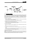
7.2 TELEPHONE INTERFACES
The Trilogy 500-19 range of equipment provides full DTMF telephone facilities when used in
conjunction with the Telos ONE “smart” telephone hybrid. To obtain the full facilities
available with the Commander system, the Telos ONE should be fitted with the Telos Super
Auto Answer (SAA) option. During the installation it is important to remember that the
Telephone Interface must be connected to the matrix via a panel port wired with 4 pair cable.
The connection is not just audio / 4-wire, there is a data exchange between the matrix and
telephone interface. Each 500-19-10 Rack Mounting Frame can contain a maximum of three
500-19-00 Telephone Interface Cards. An installation specification for the frame is given
below.
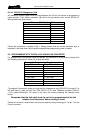
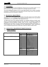
Trilogy 500-19-10 Telephone Interface Frame
Dimensions 485mm wide x 44.5mm high x 440mm deep
(excluding connectors)
19” x 1RU rack mounting
Mains Input 90 – 250 V ac, 50-60Hz
Power Consumption 45VA
Connector Detail (per channel)
Active link to matrix D9 Fixed Plug
Audio to Telos Hybrid 3 pin XLR Fixed Plug
Audio from Telos Hybrid 3 pin XLR Fixed Socket
Control link to Telos Hybrid D15 Fixed Plug
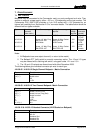
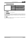
Each connection to a telephone line requires a separate Telos ONE hybrid. An installation
specification is given below.
Telos ONE Telephone Hybrid
Dimensions 485mm wide x 44.5mm high x 240mm deep
(excluding connectors)
19” x 1RU rack mounting
Mains Input 100 – 240 V ac, 50-60Hz
Power Consumption 90mA – 50mA
Connector Detail
Audio to Trilogy Telephone Interface 3 pin XLR Fixed Plug
Audio from Trilogy Telephone Interface 3 pin XLR Fixed Socket
Control link to Trilogy Telephone Interface 15 way D Fixed Socket
Telephone Line RJ-11
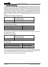
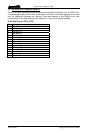
If the Telos equipment is purchased separately (i.e. not via Trilogy) it is important to specify
to your supplier that the equipment is for connection to a Trilogy Commander system. This
allows the correct software versions and hardware modifications to be fitted.
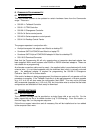
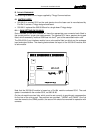
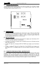
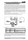
A typical system interconnection diagram is given below.