


Commander Installation Guide
Page 24 of 81
Issue 9
Trilogy Communications Limited
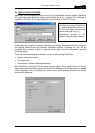
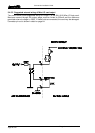
3.4.3 SERIAL LINK (RS232 / RS422)
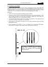
The current version of PC connector plate, which is fitted on the rear right hand side of the
Commander Matrix frame, provides either RS232 or RS422 connection capability. The
factory default setting is RS232: this may be changed by removing the 4 fixing screws,
withdrawing the rear connector assembly and moving the PCB mounted jumper links to the
alternate position. Most computers are fitted with D9 fixed sockets for the serial COM port.
For older models equipped with a D25, suitable adaptors may be easily obtained.
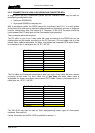
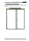
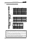
RS232 configuration.
Commander Sub D9
Fixed Socket - Pin
Function PC COM Port
D9 Fixed Socket
1 DCD 1
2 TX 2
3 RX 3
4 DTR 4
5 0V or GND 5
6 DSR 6
7 CTS 7
8 RTS 8
9 n/c 9
Case
Note: Pin 1 through to Pin 8 MUST be wired 1:1. CAT 5 cable is suitable for most
applications.
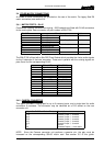
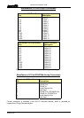
RS422 configuration.
Commander Sub D9
Fixed Socket Pin (+,-)
Function
Notes
4,8 422 in, +,- Pair 1 (RX)
6,1 422 out, +,- Pair 2 (TX)
7,2 422 RTS +,- Pair 3
5,9 422 CTS +,- Pair 4
3 Chassis
Connection to external equipment will depend on the manufacturer and model of RS422
card fitted. The table above only relates to the matrix.
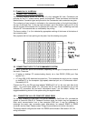
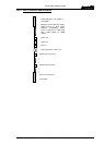
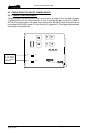
3.4.4 ALARMS
These are provided on a 9 way D type fixed socket on the rear of the matrix. The function of
the output is software controlled from the 500-08-10 Changeover card. The output is a
normally made, solid state relay contact. Maximum current rating is 120mA.
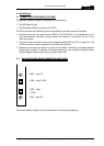
Commander
D9 Fixed Socket - Pin
Function
Notes
1,6 Right side OK Pair 1
2,7 Left side OK Pair 2
4,8 C/O Card OK Pair 3
5,9 Left side selected Pair 4
3 Chassis