


Commander Installation Guide
Issue 9 Trilogy Communications Limited Page 37 of 81
5.4 500-41-XX SERIES DESKTOP PANELS
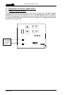
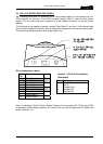
Early desktop panel were DC powered from a mains power supply unit connected via a mini
DIN connector on the rear. From 2003 onwards, panels have an internal mains power
supply. The only remaining user connection is to the Headset connector on the rear of the
desktop.
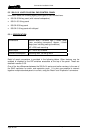
The following wiring applies to panels marked "Mod State 2" and later. Earlier panels had
pins 4 and 6 transposed internally, with corresponding changes to the interconnecting cable.
The later wiring allows operation over longer cable runs.
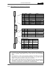
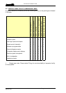
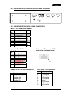
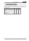
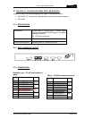
RJ-45 connection to Matrix
RJ-45
Pin
Function
1 Panel Data out + Pair
1
2 Panel Data out -
3 Panel Data In + Pair
2
6 Panel Data In -
5 Panel Audio out + Pair
3
4 Panel Audio out -
7 Panel Audio in + Pair
4
8 Panel Audio in -
n/c Cable Screen
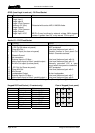
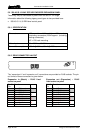
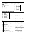
Headset - 5 Pin XLR Fixed Socket
(Rear panel)
Pin Function
1 Mic IN (Screen)
2 Mic IN
3 Headset Gnd
4 Headset Out
5 Headset Out
Note: As delivered, 500-41 Series Desktop Panels will not operate with T-Edit (early DOS
configuration editor) based systems. An internal link must be changed and full details are
given in Section 10.1.