


3-5
Catalyst 2950 Desktop Switch Software Configuration Guide
78-11380-05
Chapter 3 Getting Started with CMS
Front Panel View
Cluster Tree
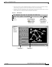
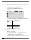
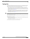
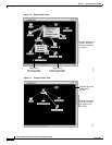
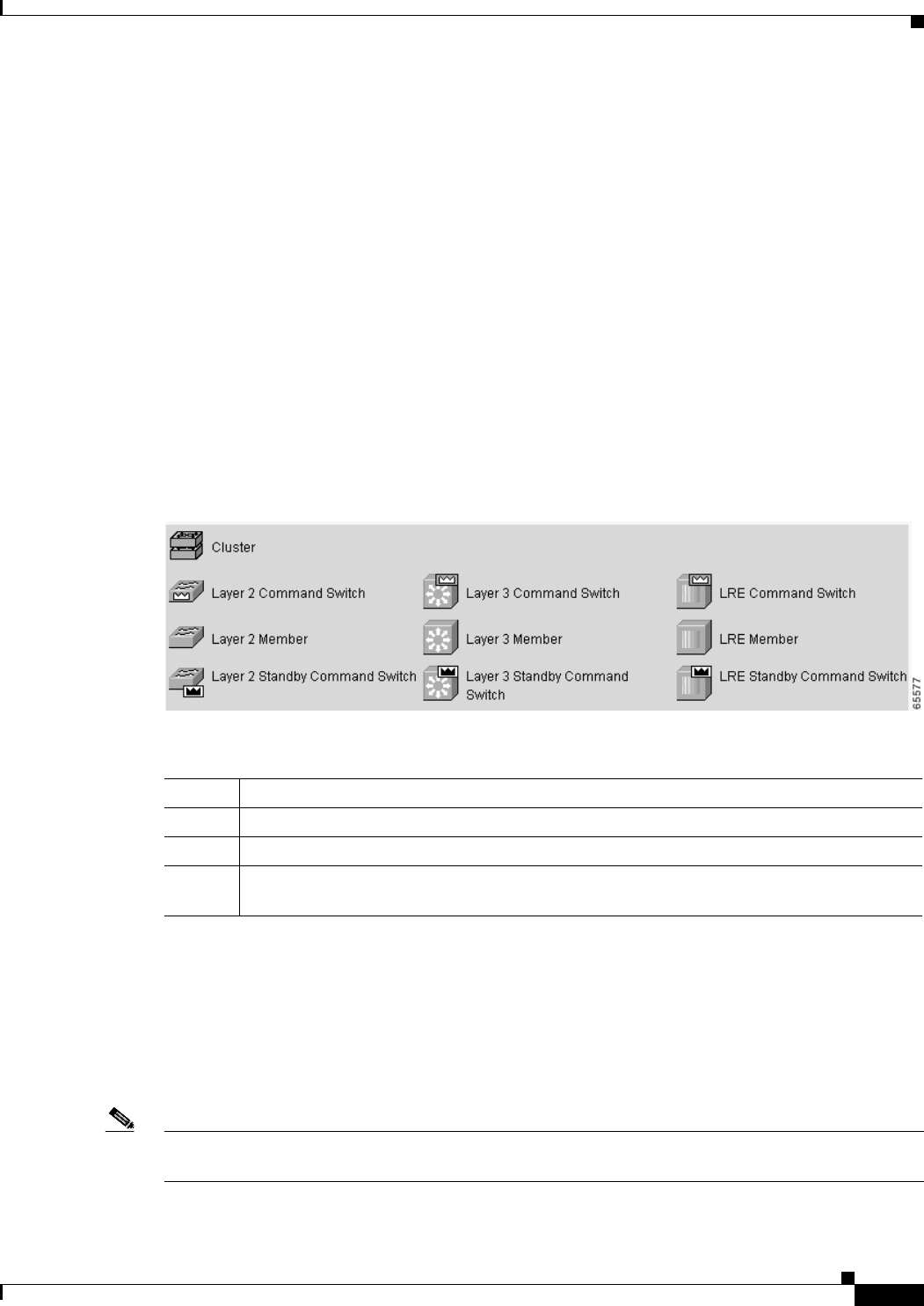
The cluster tree (Figure 3-2) appears in the left frame of the Front Panel view and shows the name of the
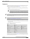
cluster and a list of its members. The sequence of the cluster-tree icons (Figure 3-4) mirror the sequence
of the front-panel images. You can change the sequence by selecting View > Arrange Front Panel. The
colors of the devices in the cluster tree show the status of the devices (Table 3-1).
If you want to configure switch or cluster settings on one or more switches, select the appropriate
front-panel images.
• To select a front-panel image, click either the cluster-tree icon or the corresponding front-panel
image. The front-panel image is then highlighted with a yellow outline.
• To select multiple front-panel images, press the Ctrl key, and left-click the cluster-tree icons or the
front-panel images. To deselect an icon or image, press the Ctrl key, and left-click the icon or image.
If the cluster has many switches, you might need to scroll down the window to display the rest of the
front-panel images. Instead of scrolling, you can click an icon in the cluster tree, and CMS then scrolls
and displays the corresponding front-panel image.
Figure 3-4 Cluster-Tree Icons
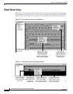
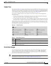
Front-Panel Images
You can manage the switch from a remote station by using the front-panel images. The front-panel
images are updated based on the network polling interval that you set from CMS > Preferences.
This section includes descriptions of the LED images. Similar descriptions of the switch LEDs are
provided in the switch hardware installation guide.
Note The Preferences window is available if your switch access level is read-only. For more information about
the read-only access mode, see the “Access Modes in CMS” section on page 3-29.
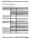
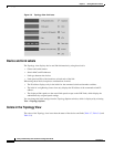
Table 3-1 Cluster Tree Icon Colors
Color Device Status
Green Switch is operating normally.
Yellow The internal fan of the switch is not operating, or the switch is receiving power from an RPS.
Red Switch is not powered up, has lost power, or the command switch is unable to communicate
with the member switch.