


20-2
Catalyst 2950 Desktop Switch Software Configuration Guide
78-11380-05
Chapter 20 Configuring SPAN and RSPAN
Understanding SPAN and RSPAN
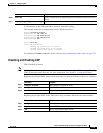
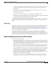
Figure 20-1 Example SPAN Configuration
Only traffic that enters or leaves source ports can be monitored by using SPAN.
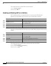
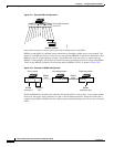
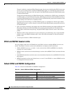
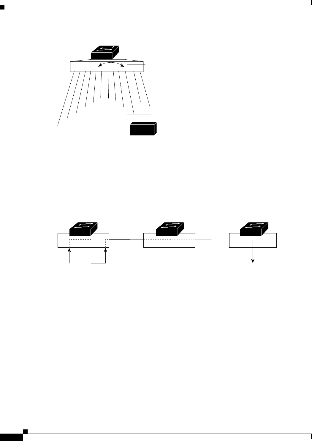
RSPAN extends SPAN by enabling remote monitoring of multiple switches across your network. The
traffic for each RSPAN session is carried over a user-specified RSPAN VLAN that is dedicated for that
RSPAN session in all participating switches. The SPAN traffic from the sources is copied onto the
RSPAN VLAN through a reflector port and then forwarded over trunk ports that are carrying the RSPAN
VLAN to any RSPAN destination session monitoring the RSPAN VLAN, as shown in Figure 20-2.
Figure 20-2 Example of RSPAN Configuration
SPAN and RSPAN do not affect the switching of network traffic on source ports; a copy of the packets
received or sent by the source interfaces are sent to the destination interface. Except for traffic that is
required for the SPAN or RSPAN session, reflector ports and destination ports do not receive or forward
traffic.
1 2 3 4 5 6 7 8 9 10 11 12
Port 5 traffic mirrored
on Port 10
3
2
1
4
5
67
8
9
11
12
10
Network analyzer
43580
Source switch Intermediate switch Destination switch
74727
RSPAN
source port
RSPAN
destination port
Reflector
port
RSPAN
VLAN
RSPAN
VLAN