


Wallboard Installation and Maintenance Wallboard 10
Compact Contact Center Installation & Maintenance
40DHB0002USBG Issue 1 (11/14/2001) Wallboard Installation and Maintenance
•
Page 44
System Wiring
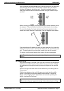
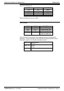
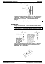
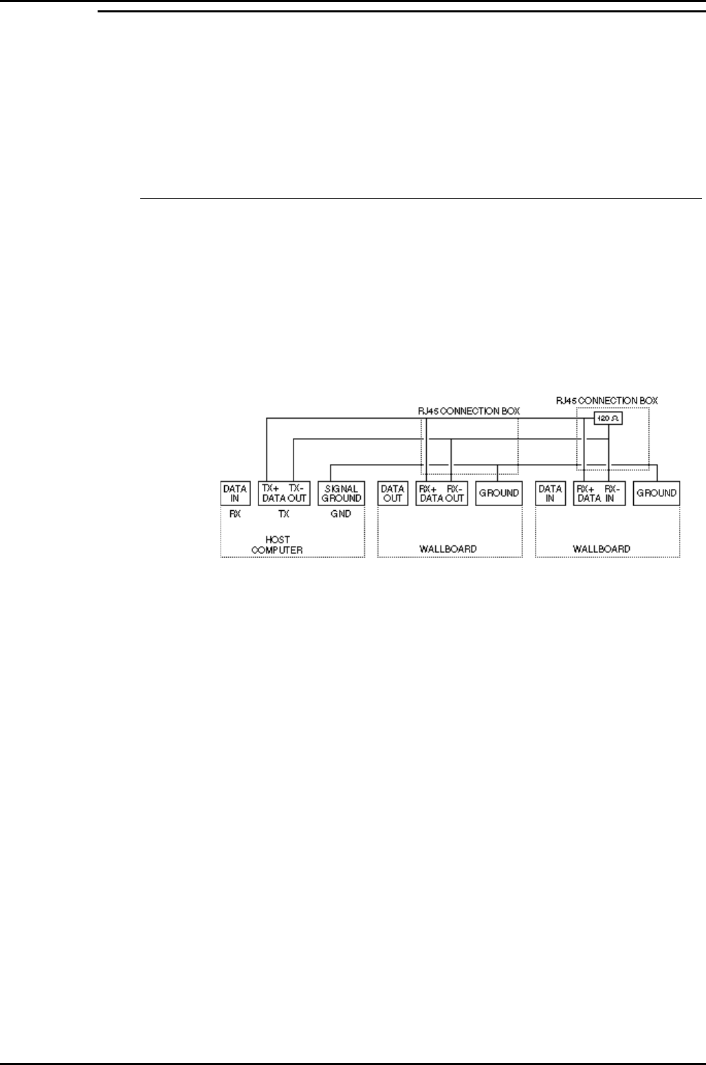
The principle for wiring up your display wallboards is that the PC output port
is connected to the input of each wallboard. See Figure 7.
The connection is RS485 and the screen of the cable is connected to the
wallboard signal ground, which is floating.
The wallboard housing frame ground is connected to earth by the power
cable
RS485
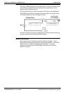
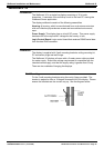
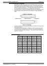
This standard officially allows 30 wallboards to be connected via a RS485
transmission cable of up to 1200 Meters to a PC RS485 port.
The PC TX+ is connected to the wallboard RX+; similarly, the PC TX- is
connected to the wallboard RX-. The recommended technique is to run a
screened cable from the PC to the nearest wallboard, then from this
wallboard to the next nearest wallboard etc. At the last wallboard on the
bus, it is necessary to connect a 120Ω terminating resistor between the
wallboard RX+ and RX- connections within the RJ45 connection box. See
the diagram below.
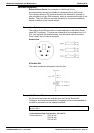
The installation technique is that data input of each display is electronically
connected to the transmit output of the PC.