


Wallboard Installation and Maintenance Wallboard 22
Compact Contact Center Installation & Maintenance
40DHB0002USBG Issue 1 (11/14/2001) Wallboard Installation and Maintenance
•
Page 34
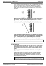
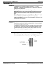
RS485 Serial Connection
The RJ45, RS485 flying lead is one meter long. It cannot be removed from
the Wallboard; therefore, this must be taken into consideration for the
location of the RJ45 terminal box.
Fit the RJ45 terminal box within one meter of the center of the Wallboard.
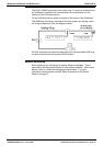
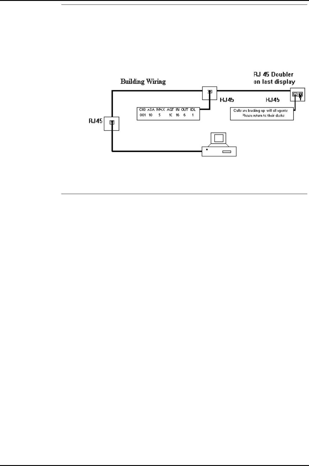
The Wallboard should be connected to the host system by utilizing a drop
off wiring configuration (See the diagram below).
All RJ45 sockets should be wired identically with the terminated RJ45 plug
on the final socket with the supplied RJ45 doubler.
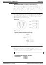
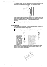
Network Addressing
Each display can be configured to display different messages. This is
achieved by allocating each display its own network address. Within each
display, there is a board containing eight dip-switches. For more
information see the section entitled "Serial Connection & Dip-Switch
Details" on page 37.