


Wallboard Installation and Maintenance Wallboard 22
Compact Contact Center Installation & Maintenance
40DHB0002USBG Issue 1 (11/14/2001) Wallboard Installation and Maintenance
•
Page 37
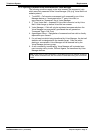
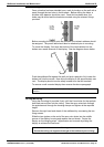
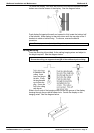
Serial Connection & Dip-Switch Details
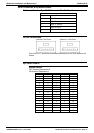
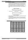
Wallboard Terminal Box RJ45 Connector Pin Out Details
Pin
2 Signal Ground
3 Sign Rx+ Input
4 Sign Tx+ Output
5 Sign Tx- Output
6 Sign Rx- Input
7–
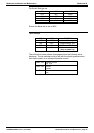
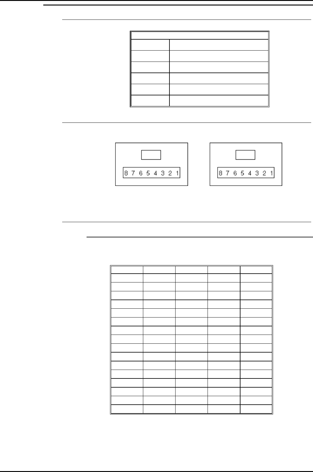
Pin out Connections
Wallboard x
RJ45 Socket Wallboard x+1 RJ45 Socket
Pins from 2 to 7 should be connected identically from all RJ45 boxes to all
others.
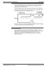
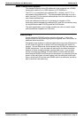
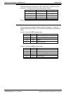
Dip-Switch Details
Network Address
OFF Position Represents 0
ON Position Represents 1
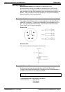
SW4 SW3 SW2 SW1 ADDRESS
00000
00011
00102
00113
01004
01015
01106
01117
10008
10019
101010
101111
110012
110113
111014
111115