


Wallboard Installation and Maintenance Wallboard 10
Compact Contact Center Installation & Maintenance
40DHB0002USBG Issue 1 (11/14/2001) Wallboard Installation and Maintenance
•
Page 42
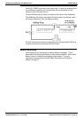
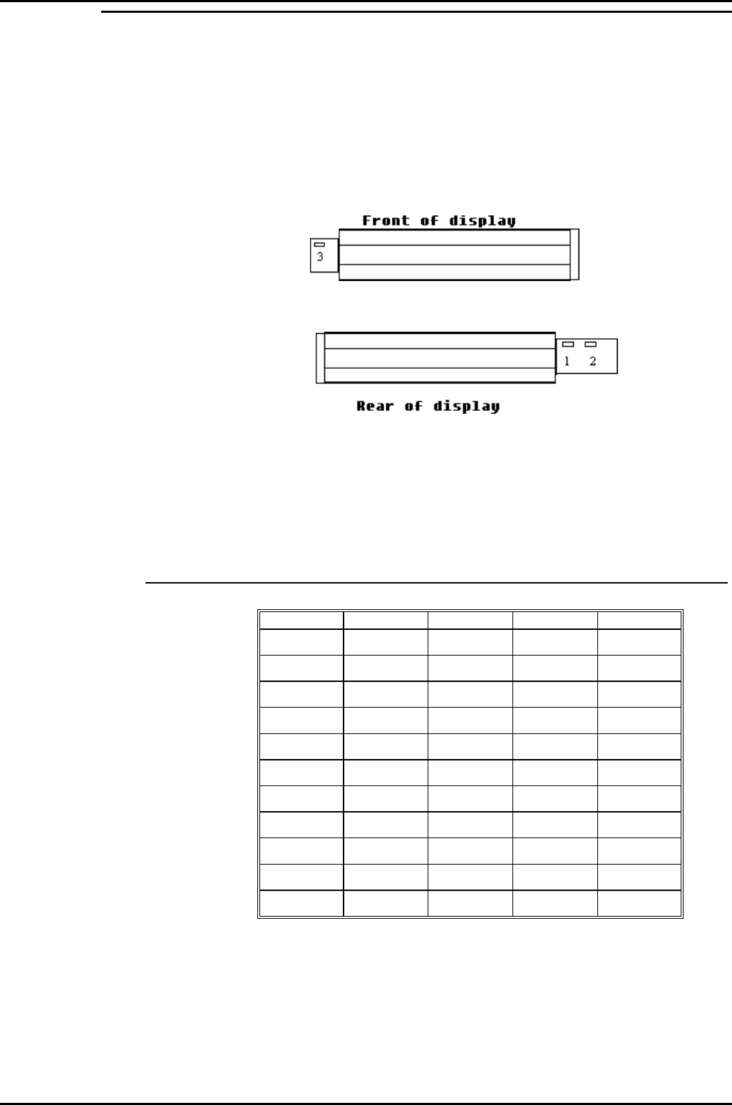
Serial Connection and Configuration
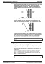
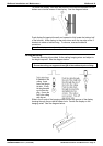
An RJ45 junction box is provided as standard, alternatively if required an
RJ45 coupler and 2 way adapter can be used. The serial cable is normally
connected to the logic board for RS485 operation, check label on rear of
display for specific configuration. The serial communications lead from the
PC is connected to the junction box as shown later in this manual.
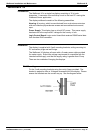
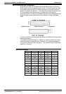
Following section 2.3 below, but changing the dip-switch settings as per the
diagram below can do modifications to the network numbers and baud
rates.
1. RS232 Connection 2. RS485 Connection 3. Dip-Switches
To set the network number requires access to the Wallboard 10 logic board
as explained above.
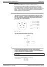
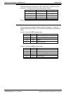
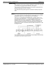
To address individual displays in a network, a network number can be set
on the dip-switch on the logic board. Network 0 is a general address and
will accept all data from the host system. The network number is set using
switches 1,2,3 and 4.
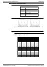
Dip-switch Number
1234Network
OFF OFF OFF OFF 0
ON OFF OFF OFF 1
OFF ON OFF OFF 2
ON ON OFF OFF 3
OFF OFF ON OFF 4
ON OFF ON OFF 5
OFF ON ON OFF 6
ON ON ON OFF 7
OFF OFF OFF ON 8
ON OFF OFF ON 9
ETC….