


Wallboard Installation and Maintenance Wallboard 22
Compact Contact Center Installation & Maintenance
40DHB0002USBG Issue 1 (11/14/2001) Wallboard Installation and Maintenance
•
Page 32
Wallboard Installation and
Maintenance
Wallboard 22
Introduction
The Wallboard 22 is a two line by 22-character tri-color Wallboard. It
connects via a multi-drop circuit to the host PC running the Wallboard
Server application.
The display wallboard consists of the following assemblies.
Housing: A housing that is manufactured from an aluminum extrusion with
anti reflective polycarbonate screen and removable plastic end caps.
Power Supply: 9V DC switch mode power supply assembly incorporating
an RJ45 chassis mounted data connector. The power supply is
configurable for use from either 120V AC or 240V AC (NOMINAL
VOLTAGES) supplies.
Logic Control Board: Logic control board that receives RS485 serial data
from the data RJ45 connector.
Display Board Assembly: Tri-color display board assembly, which
consists of three display boards which, are connected one to the other by a
fiber optic link. The left-hand display board receives display data from the
logic control board, via a fiber optic link and it outputs data to the next
display board etc.
Each display board consists of decoding and LED row and column circuitry
which drives the LED matrix consisting of 18 5x8 LED blocks.
Installation
Before commencing installation, please check from the packing list that all
parts are included.
Packing List:
1 x Wallboard 22
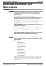
2 x Wall mount brackets
2 x Spun hanging wires
4 x Cavity rawl plugs
4 x Screws
2 x Eyehole bolts
2 x Masonry rawl plugs
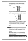
2 x Housing clamps
1 x RJ45 Terminal Box
1 x IEC Power lead
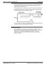
Before commencing installation, please take a couple of minutes ensuring
that the final location of the display will be both safe and practical for the
customer. Also check that the power socket provided is suitable for this
type of display.