


Section 7 DriverSection 7 Driver
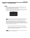
7. Driver (BLD72 SERIES DRIVER)
BILEVEL DRIVE
The basic function of a step motor driver is to provide the rated motor phase current to the
motor windings in the shortest possible time. The bilevel driver uses a high voltage to get a
rapid rate of current rise in the motor windings in the least amount of time. When reaching
the preset trip current, the driver turns off the high voltage and sustains the current from
the low voltage supply.
HALF-STEP/FULL-STEP
Users have a choice of full-step operation or half-step operation. Full-step operation
occurs by energizing two phases at a time, rotating a typical motor 1.8 degrees per step.
Half-step operation occurs by alternately energizing one, and then two, phases at a time,
rotating the motor 0.9 degrees per step. Full-step operation is suggested for applications
that specifically require that mode, such as when retrofitting existing full-step systems.
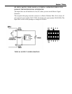
To activate Full Step, jumper PIN 7 and PIN 8 on Driver Terminal Block.
MOTOR ON/OFF INPUT (Internally Connected)
The motor on/off input allows de-energizing a motor without disturbing the positioning
logic. After re-energizing the motor, a routine can continue. This reduces motor heating
and conserves power, especially in applications where motors are stopped for long periods
and no holding torque is required. If holding torque is required (such as when lifting a
load vertically), then this function should not be used. This output is internally connected
to the Indexer. See Section 8 Command Descriptions for further information on Current
Hold Command.
FAULT PROTECTION
There are 3 types of fault detection. When a fault is detected, the driver turns off the motor
current and the red Fault LED indicates which type of fault occurred. (Located on the top
of the driver pack.)
1 LED - Slow Blink shorted wire in the motor or cable
2 LED - Fast Blink open wire in the motor or cable
3 LED - ON Steady ground fault (voltage shorted to 0V)
FAULT LED
If the driver goes into a fault condition, the fault may be reset by turning the power OFF
for at least 15 seconds or by pulling the RESET FAULT input (terminal 4) to a logic “0"
for at least 100ms.
Section