


Section Section 44 System ProgrammingSystem Programming
5454
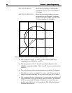
G28 Rapid move in the Z axis to Machine
Coordinate Z=-1 followed by a rapid move
in the XY plane to Machine Coordinate
X=1, Y=1
G29 X2 Y3 Z-2 Rapid move in the XY plane to Program
Coordinate X=2, Y=3 followed by a rapid
move in the Z axis to Program Coordinate
Z=-2
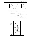
When using G29, there are several things to keep in mind:
• You do not need to specify all three coordinates, only the ones for which you
want movement.
Example:
G29 X4.0 Y3.0 Moves the tool to Program Coordinates
X=4.0, Y=3.0, leaving the Z position
unchanged.
• The interpretation of the coordinates depends on the G90/G91 command in
effect.
G43, G44, G49, M06 Tool Change and Tool Length Compensation
Commands
LC supports tool changes and tool length compensation. Tool length
compensation lets LC account for differences in tool lengths, so the G-Code
program can be created without regard to specific tool lengths (except for possible
interference problems).
THESE COMMANDS ARE NOT FOR THE NOVICE CNC USER. WHEN
NOT PROPERLY USED, TOOL LENGTH COMPENSATION CAN CRASH
THE MACHINE TOOL, CAUSING SERIOUS DAMAGE TO YOUR
WORKPIECE OR MACHINE TOOL.
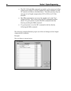
When applying tool length compensation, LC uses the Length Offsets defined in
the Tooling Setup dialog box. See “Tooling Settings” in the Initial Setup section
for more information on defining your tools.
For tool length compensation to work properly, LC must know what tool is in use
at all times, including the tool that’s loaded when you start running a G-Code file.
Therefore, before you run a G-Code file that uses tool length compensation, you
must first choose your starting tool from the Current Tool pull-down menu on the
main screen.
To indicate tool changes in the G-Code file, use the M06 command as follows:
M06 Tn
where n is the tool number in the Tooling Setup dialog box.
Example: