


Section 7 DriverSection 7 Driver
6. I/O CONNECTIONS
WIRING
BE VERY CAREFUL WHEN DOING ANY WIRING. IMPROPER WIRING WILL
DAMAGE THE MOTOR SIGNAL GENERATOR.
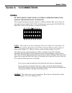
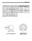
The receptacle that plugs unto this connector is a Molex-Waldom Mini –Fit Jr. Series 16
pin receptacle (part number 39-01-2160), the female pins (part number 39-00-0039). The
input lines as seen on the package as arranged as follows:
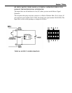
INPUT – The connector for up to 8 input lines. The most common use of the input is for
limit or safety switches. These lines are all TTL level inputs. When a switch is open, its
input signal is High (+5V). When a switch is closed, its input signal is Low (0V).
All switches can be wired normally open (NO) or normally closed (NC), Software
Selectable. Each Normally Closed System must have all unused inputs wired to ground
(0V). Each Normally Open System must have all unused inputs left Open. When any of the
inputs line are open the Red Limit Light will illuminate and a signal will be sent to the host
PC to indicate which input line(s) went high.
If you are not using the input lines, the limit light will always be illuminated.
If you experience unexpected limit errors, make sure that the Signal Generator
Model 401A option is chosen in the System Options setup screen and all input lines
are properly defined in the Input Lines Setup screen.
OUTPUT – The connector for up to 8 output lines. These lines are all optically isolated,
TTL level outputs. Low is 0V and High is +5V.
Section