


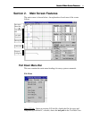


Section Section 22 Main Screen FeaturesMain Screen Features
1515
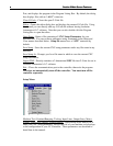
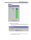
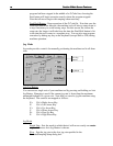
4 To zero all axes.
1. Choose the Zero All button to zero all of the coordinates
simultaneously.
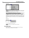
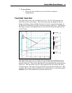
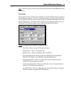
Tool Path View Port
The figure below shows the Tool Path View Port. The XY Grid represents an
aerial view of the tool envelope. The Z Scale represents the height of the tool
during machining. Green and light blue dots are used to represent the origins of
the Program and Machine (if used) coordinate systems respectively. The Machine
Envelope is shown as the light blue box on the XY Grid and by the light blue bar
on the Z Scale.
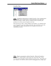
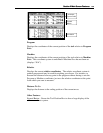
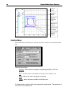
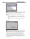
The figure below shows the Tool Path View Port during the machining process.
The bottom of the blue tool icon adjacent to the Z scale represents the current Z
position of the tool. The yellow dot on the XY grid represents the current position
of the tool. The red outline in the XY Grid represents the tool path of the entire
G-code program. The red bar along the Z Scale represents the total Z travel. Blue
represents the portion of the tool path that has already been cut. Solid lines depict
feedrate moves while dashed lines represent rapid moves.
Z Scale
XY Grid
Program
Zero
Machine
Zero
Machine
Envelope