


Section Section 44 System ProgrammingSystem Programming
4343
size of the original geometry defined in the DXF file. Note that the values
you enter for positioning the Z axis are unaffected by the scale factor.
8. Decimals - The number of decimal places to use for all coordinates. A
higher number can help eliminate extra backlash compensation moves
caused by rounding error.
9. Join Tolerance – If two drawing entities, such as two lines, are touching
end to end, LC treats them as a single feature to machine without lifting
the tool. Due to rounding or drawing error, two entities that are meant to
be joined may not actually touch end to end. The DXF import will
automatically join any entities whose endpoints are less than the Join
Tolerance apart.
10. Line Numbers – Check this box if you want the DXF import to number all
of the G-Code lines in the program it creates.
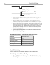
11. Incremental Depth of Cut - The incremental depth for each milling pass.
For example if the final tool down is -0.2500” and the incremental depth
of cut is 0.0625” then four passes would be cut on each feature to get to
the final depth of cut. (-0.0625, -0.1250, -0.1875, -0.2500). If the final
tool down is -0.3000” and the incremental depth of cut is 0.0625” then
five passes would be cut on each feature to get to the final depth of cut (-
0.0625, -0.1250, -0.1875, -0.2500, -0.3000).
12. Tool Up - The height (program coordinates) to which the tool will move
before rapid moves between two features.
13. Final Tool Down (Milling) - The final depth (program coordinates) to
which the tool will cut each feature.
14. Final Tool Down (Holes) - The final depth (program coordinates) to which
the tool will cut each hole.
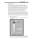
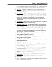
15. Program Zero Location
16. X, Y of Import File - The X and Y location in the DXF file that LC will
place at the program origin in the G-Code file.
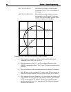
17. Lower Left of Toolpath - Defines program zero as the lower left point of
the imaginary box that envelopes all geometry contained in the DXF file.
18. Circles - Defines diameters for circles that will be drilled (at the center
point) instead of milled along the perimeter.
19. XY Feedrate - The feedrate for all milling operations in the XY plane.
20. Plunge Feedrate - The feedrate for all downward Z axis moves.
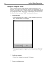
21. Choose OK.
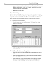
22. The G-Code will appear in the Program Listing Box and the tool path will
appear in the Tool Path View Port.