


Section Section 33 Initial SetupInitial Setup
3838
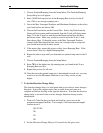
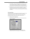
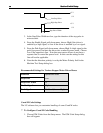
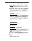
Low Step Pulse
High Step Pulse
Step Pulse Width
+5 V
0 V
+5 V
0 V
3. In the Step Pulse Width text box, type the duration of the step pulse in
microseconds.
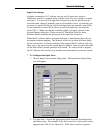
4. From the Enable Signal pull-down menu, choose High if the driver is
enabled by a high signal, or Low if the driver is enabled by a low signal.
5. From the Park Signal pull-down menu, choose High if a high signal to the
park (low power) line puts the driver into a reduced power mode. Choose
Low if the opposite is true. Note that most motor drivers do not have a
separate line to control the power level. In this case the setting for this
line will not be applicable.
6. Note that the direction polarity is set by the Motor Polarity field in the
Machine Tool Setup dialog box.
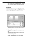
Recommended Settings for Various Stepper Motor Driver Boxes:
Function Operational State
Step Pulse
Low
Step Pulse Width
15
Enable Signal
High
Park Signal
Not Used (Low or High)
G and M Code Settings
The LC software lets you customize handling of some G and M codes.
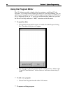
4 To Configure G and M Code Handling
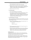
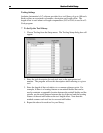
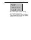
1. Choose G/M Codes from the Setup menu. The G/M Code Setup dialog
box will appear.