


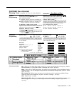
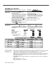
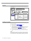
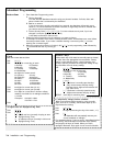
Back Panel
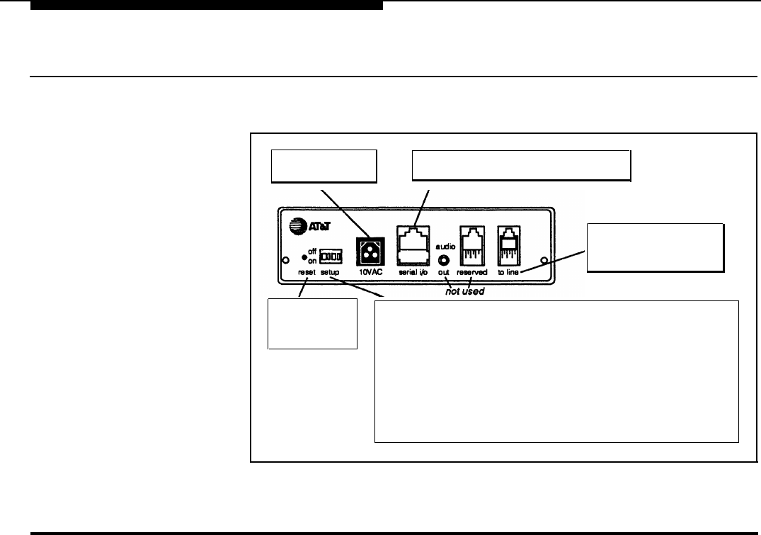
The back panel (Figure 2-2) has the switches, connectors, and jacks neces-
sary for installation.
10VAC
Connects AC power
serial i/o
Used for maintenance purposes
to line
Modular phone cord from
206 module connects here
reset
Recessed button
resets the unit
(see Appendix B)
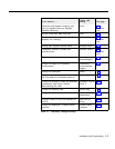
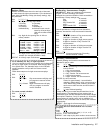
setup
Position of setup switches (on or off) determines how the unit will respond to
a power outage:
Switch
On (Down)
Off (Up)
1
Recorded announcements are
Recorded announcements are
retained up to 3 hours after erased after a power outage
a power outage occurs
occurs
2 Routes and other programmed Routes and other programmed
settings are retained up to eight settings are reset to defaults
weeks after a power outage occurs after a power outage occurs
3 Not used Not used
4
Not used
Not used
Figure 2-2 BackPanel
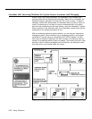
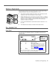
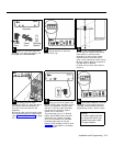
Installing the Attendant
Before starting installation:
■
Read and understand "Safety Instructions" on page 2-ii.
■ Identify Attendant extensions (see page 1-6).
■
Locate the Attendant so it is within 10 feet of the system control unit, and
within 5 feet of the AC outlet. The location must also meet the environ-
ment requirements listed in Appendix C, "Specifications."
■
Wall mounting Attendants is optional but strongly recommended.
■ If you install multiple Attendants without wall mounting, do not stack the
units.
NOTE:
Attendant installation requires skill in programming the system and the Atten-
dant. Installation and training by AT&T personnel is strongly recommended if
you do not have that skill. To request installation, please call 1 800 247-7000.
2-2 Installation and Programming