


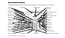

NSQ412 Four-Line Caller ID Telephone Owner’s Manual 14
Install a 9V alkaline transistor radio
battery. Be sure to install the battery
polarity correctly by observing the
drawing on the inside of the compart-
ment. Replace the battery door and
the screw.
3. Plug one end of the coiled handset
cord into the handset’s jack and the
other end into the base handset jack.
4. For wall mounting, the handset must
be retained securely in the cradle.
The handset guide must be changed
from the desk position to the wall
position. To do this, pull the handset
guide out and rotate it 180. It will now
protrude slightly, providing a tab for
the handset to rest on.
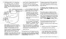
5. Connect the a. c. power adapter to
the power jack on the NSQ412. Do
not connect the adapter to the electri-
cal outlet at this time. Route the
adapter cord through the A. C.
Adapter Hook on the station’s back.
If you are installing the NSQ412 to
screws, skip down to step 12.
6. If you install the NSQ412 to the
mounting studs of a telephone wall
jack, lines 1 and 2 must be terminat-
ed to it. Lines 3 and 4 (if used) must
be terminated to a different jack.
7. Connect the short 4-conductor tele-
phone line cord supplied with the unit
to the L1/L2 jack. Route the cord
through the telephone line cord
channel on the station’s back.
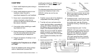
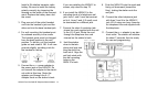
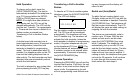
8. Hold the station
close to the tele-
phone wall jack and
plug the short line
cord into it. Align the
wall jack studs with
the wall mounting
holes on the
NSQ412’s back.
9. Push the NSQ412 onto the studs and
firmly pull downward (toward the
floor), locking the station onto the
wall jack.
10. Connect the other telephone jack
with lines 3 and 4 to the NSQ412
jack L3/L4 using one long 4-conduc-
tor telephone line cord supplied with
the telephone.
11. Connect the a. c. adapter to an elec-
trical outlet. The station will initialize
for about 7 seconds, then be ready
for use and programming.
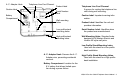
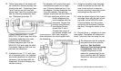
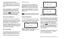
61/2
Lines 3/4
A.C. Adapter