


NSQ412 Four-Line Caller ID Telephone Owner’s Manual 13
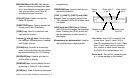
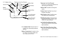
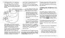
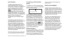
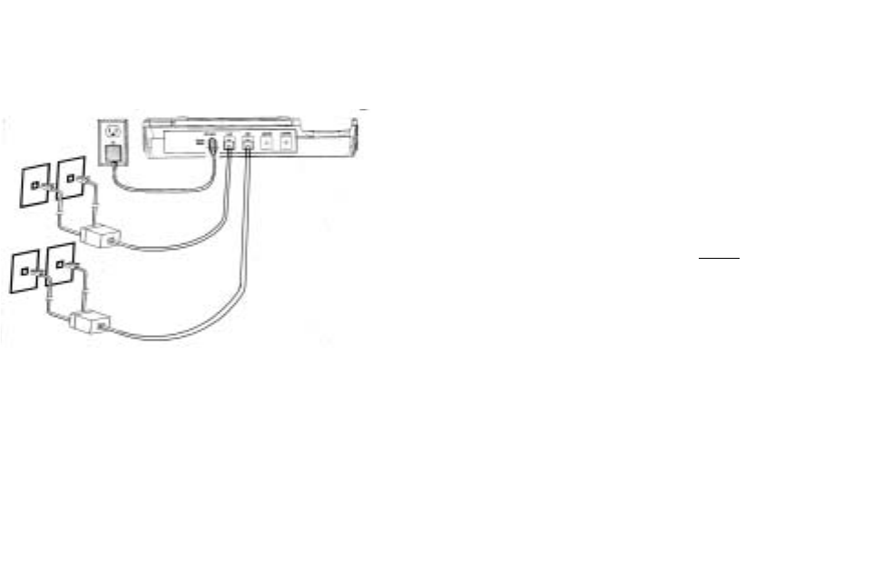
6. If telephone lines 1, 2, 3, and 4 are
all on separate jacks, two adapters
and extra telephone line cords are
necessary (not included with the tele-
phone). See the following connection
drawing.
The adapters will convert two sepa-
rate telephone jacks into a single one.
Connect telephone line 1 into the
adapter. Connect telephone line 2
into the adapter. Connect the adapter
output jack into the NSQ412 L1/L2
jack using one of the 4-conductor
telephone line cords supplied with the
telephone. Repeat this process using
the second adapter for telephone
lines 3 and 4. Connect the output of
the second adapter jack to the
NSQ412 L3/L4 jack using the other
telephone line cord supplied with the
telephone.
If your telephone wiring does
not match either of the exam-
ples above or one of their
variations, you may need to
call your telephone service
provider for assistance. They
can install the necessary
jacks wired in the correct con-
figuration.
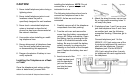
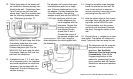
7. Once the telephone line(s)
are connected to the station,
plug the a. c. adapter into the
NSQ412 power jack. Route
the cord through the A. C. Adapter
Hook, then connect the adapter to an
electrical outlet. The station will initial-
ize for about 7 seconds, then be
ready for use.
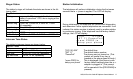
The telephone has the programming set
to the most common selections. See the
Quick Reference Card to begin using
it immediately. Refer to the
Programming section of this manual for
customizing the station’s operation and
the Feature Sections for advanced oper-
ation and use.
Installing the Telephone on a
Wall
The station may be installed onto the
studs of a telephone wall jack or onto 2
screws that are securely fastened to the
wall. Once the telephone wall jack-wiring
configuration is determined, proceed with
the installation. NOTE
: Do not connect
the a. c. adapter until instructed to do so.
The following instructions show how to
connect four telephone lines to the
NSQ412. As few as one line can be con-
nected.
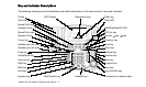
1. Carefully remove all of the telephone
components from their packing
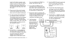
2. Turn the unit over and remove the
screw from the battery compartment
using a #2 Philips screwdriver. Open
the battery door by pressing the tab.
2 LINE ADAPTER
2 LINE ADAPTER
Line 1
Line 2
Line 4
Line 3