


24 Chapter 3 Hardware Troubleshooting
NN40160-700NN40160-700
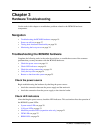
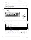
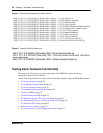
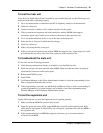
BRIM LEDs
The BRIM has one additional LED beside each RJ-48C jack. These LEDs are on when the ISDN
line is active. The figure BRIM LEDs on page 24 shows the location of the LEDs on a BRIM.
Figure 4 BRIM LEDs
For more information on the power and status LED functions, see Media bay module LEDs
(expansion units only) on page 21.
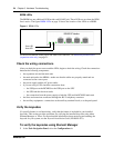
Check the wiring connections
After you check the power source and the LEDs, begin to check the wiring. Check the connections
between the following components:
• the expansion unit and the main unit
• the main unit and to the MBMs—make sure that the cables are properly seated and are
connected to the correct ports
• the power supply and the AC power outlet
• if you are using a UPS, check the connection from:
— the USB port on the BCM450 to the USB port on the UPC
— the UPS and the electrical outlet
— the connection from the power supply to both the UPS and the BCM450 main unit
• the lines and extensions connected through the RJ-21 telephony connector
• the auxiliary equipment—connections at the auxiliary terminal block, or at the patch panel
Verify the keycodes
If a specific feature is not functioning, verify that the feature is included in your installed
keycodes. This section provides procedure for verifying the installed keycodes using either
Element Manager or Telset. For more detailed information about retrieving and entering the
keycode for your system, see the Keycode Installation Guide (NN40010-301).
To verify the keycodes using Element Manager
1 In the Task Navigation Panel, select the Configuration tab.
Power LED
Status LED