


Chapter 3 Hardware Troubleshooting 23
BCM450 Troubleshooting Guide
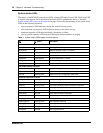
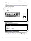
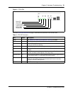
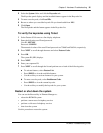
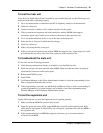
Figure 3 DTM LEDs
The table DTM LED functions on page 23 describes the functions of the DTM LEDs.
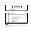
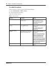
Table 4 DTM LED functions
LED Status Descriptions
Power – See “Media bay module LEDs (expansion units only)” for details.
Status – See “Media bay module LEDs (expansion units only)” for details.
In service Flashing The T1, ETSI, or PRI trunks are out of service because a loopback test is
running or the DTM is initializing.
Loopback test On A continuity loopback test is running.
Receive alarm On A problem with the received digital transmission. This half-duplex link does
not work.
Receive error On A small error as a result of degraded digital transmission. Possible causes are
an ohmic connection, water ingress, or too long a loop.
Transmit alarm On The DTM cannot transmit. The DTM sends an alarm indication signal (AIS) to
the terminating switch. This half-duplex link does not work.
Transmit error On The DTM is sending a remote alarm indication (RAI) carrier failure alarm
(CFA) to the terminating switch. If the transmit alarm is not on, this error
indicates a far-end or cable problem.
All LEDS Flashing The DTM is initializing.
Power LED
Status LED
In service LED
Loopback test LED
Receive LEDs
Transmit LEDs