


D-2
Cisco Unified IP Phone Administration Guide for Cisco Unified Communications Manager 8.6 (SCCP and SIP)
OL-23091-01
Appendix D Technical Specifications
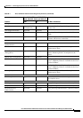
Cable Specifications
Cable Specifications
• RJ-9 jack (4-conductor) for handset and headset connection.
• RJ-45 jack for the LAN 10/100BaseT connection
• (labeled 10/100 SW on the Cisco Unified IP Phones 7962G, 7942G, 7961G and 7941G
• labeled 10/100/1000 SW on the Cisco Unified IP Phones 7961G-GE and 7941G-GE).
• RJ-45 jack for a second 10/100BaseT compliant connection
• (labeled 10/100 PC on the Cisco Unified IP Phones 7962G, 7941G, 7961G and 7941G
• labeled 10/100/1000 PC on the Cisco Unified IP Phones 7961G-GE and 7941G-GE).
• 48-volt power connector.
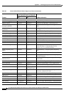
Network and Access Port Pinouts
Although both the network and access ports are used for network connectivity, they serve different
purposes and have different port pinouts.
• The network port is labeled 10/100 SW or 10/100/1000 SW on the Cisco Unified IP Phone.
• The access port is labeled 10/100 PC or 10/100/1000 PC on the Cisco Unified IP Phone.
Network Port Connector
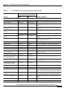
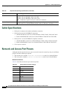
Table D-2 describes the network port connector pinouts.
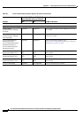
Cables Category 3/5/5e for 10-Mbps cables with 4 pairs
Category 5/5e for 100-Mbps cables with 4 pairs
Category 5e/6 for 1000-Mbps cables with 4 pairs
Note Cables have 4 pairs of wires for a total of 8 conductors.
Distance Requirements As supported by the Ethernet Specification, it is assumed that the maximum cable length
between each Cisco
Unified IP Phone and the switch is 100 meters (330 feet).
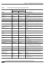
Table D-1 Physical and Operating Specifications (continued)
Specification Value or Range
Ta b l e D-2 Network Port Connector Pinouts
Pin Number Function
1 BI_DA+
2 BI_DA-
3 BI_DB+
4 BI_DC+
5 BI_DC-
6 BI_DB-
7 BI_DD+