


July 2006 About the 201i server
201i Server Hardware Installation 27
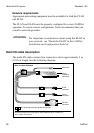
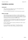
The following table identifies the purpose of each connector on the
NTRH0912
1
multi I/O cable.
Note: Labels on the RJ-45 cables distinguish the CLAN and ELAN
connectors.
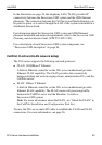
1.For customers in EUED countries: see Appendix A, “RoHS part conversion table,” to look up part
numbers for RoHS-compliant parts that are equivalent to the non-RoHS-compliant parts described in
this guide.
Connector type Purpose
50-pin amphenol This connector establishes the connection between
the Meridian 1 or Succession 1000 Media Gateway
or Media Gateway Expansion backplane and the
ELAN hub, the CLAN hub, and the modem.
10Base-T
(RJ-45)
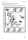
This connector provides a 10 Mbit/s Ethernet
connection between the 201i server and the
Meridian 1 switch or Succession 1000 system. This
connection allows the exchange of call control
information between the server and the Meridian 1
switch or Succession 1000 system.
For more information about the ELAN, see “About
the ELAN” in the CallPilot Installation and
Configuration Task List.
10/100Base-T
(RJ-45)
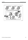
This connector provides a network connection for
user desktop computers, to enable use of the
unified messaging and fax messaging features
LAN-based server administration
ATTENTION
If you need Ethernet 100Base-T operation at
100 Mbit/s on large Meridian 1 systems (such as
Option 51), you must install the NTRH3501
backplane (tip and ring) cable. For more information,
see Chapter 4, “Installing the 201i server in a large
Meridian 1 system.”