


About the 201i server Standard 1.03
18 CallPilot
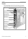
The following table describes each faceplate feature:
Faceplate feature Description
Mouse connector The mouse connector is a standard PS/2 connector and
is hot-pluggable.
Lock latches Lock latches at the top and bottom of the faceplate
secure the server to the backplane of the Meridian 1
switch or the backplane of the Succession 1000 Media
Gateway or Media Gateway Expansion.
Keyboard connector The keyboard connector is a standard PS/2 connector
and is hot-pluggable.
Infrared port For future use.
Monitor connector The monitor connector is a standard, high-density,
15-pin female connector.
Power status LED The LED indicates two server states:
the completion of self-test diagnostics
when it is safe to remove the server from the
Meridian 1 switch or Succession 1000 Media
Gateway or Media Gateway Expansion
MPC card status
LEDs
There is an LED for each MPC card slot. The following
list describes each LED status:
Off: The MPC card is not receiving power. It is safe
to remove the card.
On: The MPC card is in use. It is not safe to remove
the card.
Off, then on: The MPC card has been recognized by
the 201i server software and has been powered up.