


,QVWDOOLQJD'LVSOD\ 8QLW
BusinessPhone Call Centre Supervisor - Standard
Installation Guide
EN/LZT BS 102 063/S R2B
42
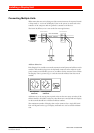
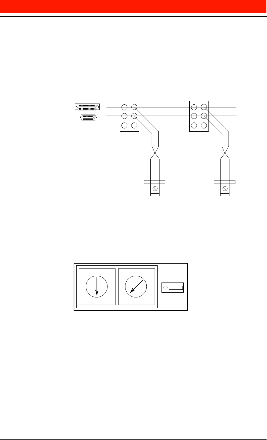
&RQQHFWLQJ0X OWLS OH8QLWV
When more than one unit is being used the connections must be repeated in mul-
ti drop mode i.e. receive of all Display Units in the system is connected to the
transmit of the computer and the ground is common to all devices.
The Serial In (White) wire is not needed in most applications.
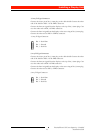
Address Selection
Each Display Unit includes a network communication Eprom and address switch
module. This module plugs into the keyboard connector socket adjacent to the
power connector and enables you to set an address for the associated unit. When
the Display Unit is powered up, it reads the network address from the switch
module.
Addresses are set by setting the required values on the two rotary switches of the
address module. An address can be any value between 01 and 99 and each display
in the network should have a different address number.
The maximum number of displays that can be connected to a single PC Serial
Port will depend on the type of display and baud rate used to transfer informa-
tion.
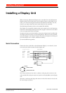
Red - Serial Out
Black - Ground
Display Unit
Display Unit
PC Serial Port
Connector
Terminal Box
Terminal Box
Power
Connector
Least significant
address bit
Most significant
address bit
0
2
3
1
4
7
6
8
5
9
0
2
3
1
4
7
6
8
5
9