


Connecting external alarm indicators and auxiliary power
Issue 3 January 2008 89
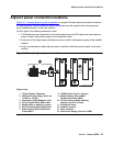
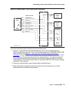
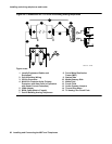
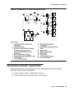
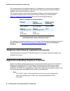
Figure 43: Sample Issue 1 IPSI-2 alarm cable connectivity
To connect the external alarm indicators and the auxiliary power:
1. Connect 1 major (Brown-White and White-Brown) and 1 minor (Orange-White and
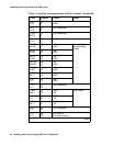
White-Orange) alarm input pair to the trunk/auxiliary field from the TN2312BP Adapter DB9
alarm connector. See Table 14: Alarm Inputs at TN2312BP Adapter DB9 Alarm
Connector on page 90. Alarms can be generated on adjunct equipment, sent to the Avaya
media gateway, and recorded and reported as “external alarms.” The adjunct equipment
must provide an isolated contact closure across the alarm leads provided by the Avaya
media gateway. The contact must be rated at a minimum of 60 VDC with a current carrying
capacity of 5 mA minimum.
2. Connect an external alarm output (Green-White and White-Green).
3. Note which device connects to which alarm and give this information to your Avaya
representative for troubleshooting purposes.
Contact
Closure on
IPSI-2
XFER48 BL-W
(-48VDC 120mA max)
GRD W-BL
XTALMA G-W
XTALMB W-G
Major (~AP1) W-O
Minor (~AP2) O-W
GRD W-O
GRD W-BR
-48V
GRD
XTALMA
XTALMB
Major
Minor
GRD
GRD
DB9 Alarm Cable
Cross Connect
808A
Emergency
Transfer
Panel
Alarm Bell,
Light, or
Indicator
UPS Alarms
Isolated
Contacts
60VDC, 5mA
Pin #
1
2
7
8
4
5
6
3
cydlips2 KLC 111104
48VDC
750mA