Installing sneak current and off premise protection
Issue 3 January 2008 57
Installing sneak fuse panels
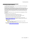
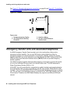
For general information, see Installing sneak current and off premise protection on page 54.
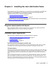
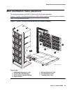
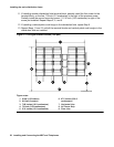
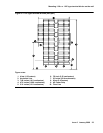
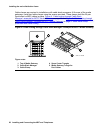
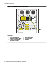
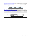
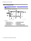
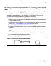
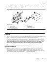
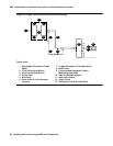
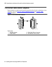
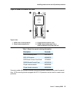
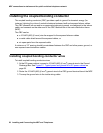
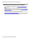
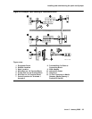
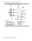
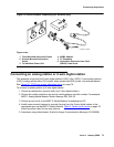
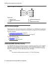
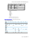
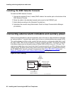
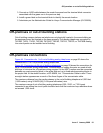
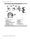
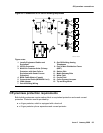
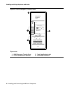
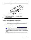
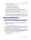
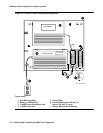
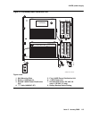
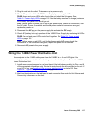
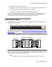
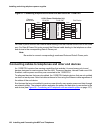
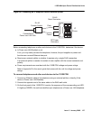
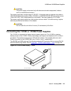
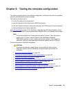
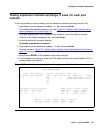
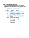
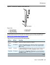
Figure 26: Model 507B sneak fuse panel
on page 55, or equivalent, is recommended for sneak
current protection. The panel contains two 25-pair connectors, fuse removal tool, and fifty
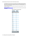
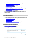
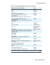
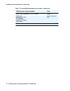
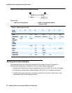
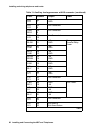
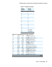
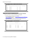
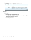
220029 sneak fuses (and two spares). See Table 6: Sneak fuse connector pinout
on page 56
for pinout data.
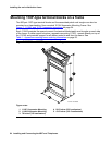
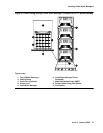
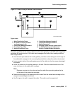
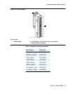
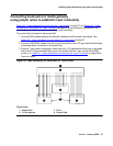
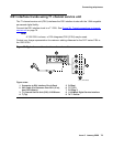
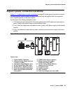
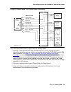
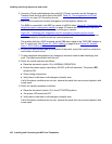
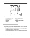
To install sneak fuse panels:
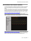
1. Locate the 507B near the network interface or the main distribution frame (MDF).
2. Hold the panel against the mounting surface and mark the mounting screw locations. Drill
pilot holes at the marked locations and partially install a locally obtained #12 x 3/4-inch
screw into the two bottom mounting slots.
3. Slide the sneak fuse panel onto the mounting screws and tighten the screws securely.
4. Install a locally obtained #12 x 3/4-inch screw into the top two mounting slots and tighten
securely.
5. Repeat the procedure for each sneak fuse panel.
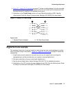
6. Secure the B25A cable to the panel with the captive screw on the connector and a supplied
cable tie.
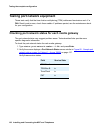
45/20 20
46/21 21
47/22 22
48/23 23
49/34 24
50/25 25
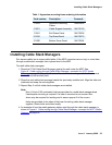
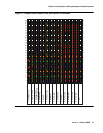
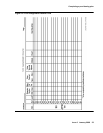
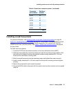
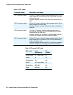
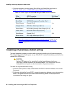
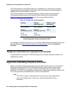
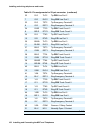
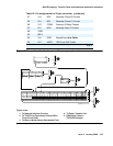
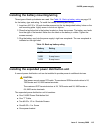
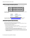
Table 6: Sneak fuse connector pinout (continued)
Connector
pin numbers
Pair/fuse
number
2 of 2