Testing port network equipment
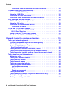
Issue 3 January 2008 137
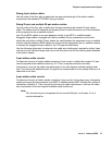
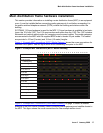
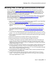
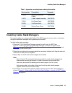
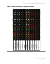
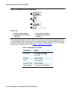
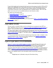
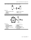
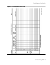
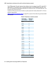
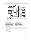
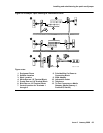
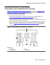
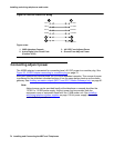
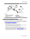
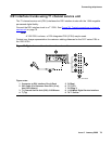
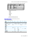
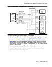
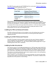
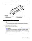
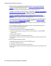
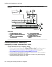
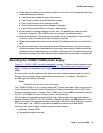
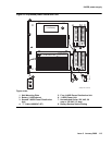
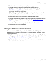
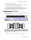
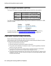
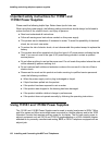
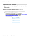
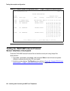
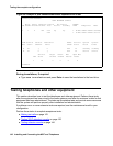
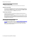
Figure 60: Sample port network status screen for Cabinet 1—Avaya S8500
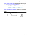
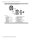
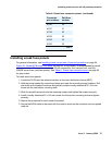
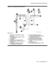
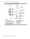
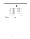
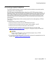
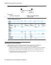
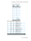
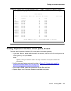
Checking circuit pack configuration
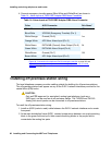
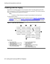
The list configuration report provides a list of circuit packs connected to the configuration and
recognized by the software. To check circuit pack configuration:
1. Type list configuration all and press Enter.
2. Verify the screen displays list configuration similar to Figure 61: Sample system
configuration screen — Page 4, Avaya S8700 Multi-Connect on page 138. Make sure the
software is communicating with each circuit pack (except power supply circuit packs). Do
not attempt to correct any problems until after the diagnostic tests that you run later in the
configuration tests.
3. Note any boards with a VINTAGE column entry of NO BOARD or CONFLICT.
A u indicates unassigned ports, and a number indicates the port has been translated.
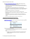
status port-network 1
PORT NETWORK STATUS
Major Minor Warning Carrier PN Control FIBER-
PN Alarms Alarms Alarms Locs Active Standby LINK Endpoints Mode
1 1 0 195 01A up up 1 B-PNC 01B02-03E04 standby
01B 1 A-PNC 01A01-01E04 active
TDM Service Control Dedicated TONE/ Service System System
Bus State Channel Tones CLOCK State Clock Tones
A in y n 01B in standby standby
B in n y 01A in active active
Service Major Minor Bus Open Bus
PKT State Alarms Alarms Faults Leads
1 in n n 0 0
Command: