


Issue 3 January 2008 29
Chapter 3: Installing the patch panel
Installing patch panels
This chapter is for installations using a patch panel rather than a main distribution frame for
connections to the building phone network and the public switched telephone network (PSTN).
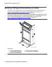
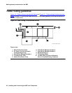
Patch panels are arrays of RJ45 jacks and associated B25A cables. The panels accommodate
2-wire, 24-port DCP/analog port boards and 8-port analog trunk boards. The panels are
mounted either below or above the media gateway stack. You cannot mount patch panels in
between media gateways.
Note:
Note: You do not have to mount the patch panels in the same rack as the media
gateways. You can mount the panels in telephone closets as appropriate.
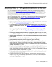
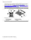
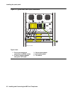
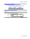
For more information, see Figure 10: Typical RMC patch panel installation
on page 30 while
you perform this procedure.
To install patch panels:
1. Use the supplied mounting screws to mount the patch panels on the rack below media
gateway A or above the topmost media gateway.
2. Attach B25A cables to the patch panels and the circuit pack amphenol connectors.
Note:
Note: Connect 24-port DCP or analog circuit packs to the 24-port patch panels.
Note:
Note: Connect 8-port analog trunk, “combo,” or DID trunk circuit packs to either of the
first two banks on the 8-port patch panel. If an TN2185B ISDN-BRI S/T-TE
Interface (4-wire, 8 ports) circuit pack is present, connect that circuit pack to the
third bank on the 8-port patch panel.
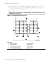
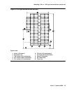
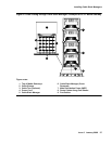
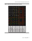
Cross-connecting the media gateway to the patch panels
Cross-connect the port circuit packs to the G650 Media Gateway patch panels or other standard
110A cross-connect equipment (Figure 11: Sample cross-connect field patch panel
connections on page 31).