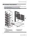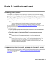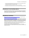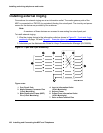
Installing and wiring telephone power supplies
130 Installing and Connecting the MDF and Telephones
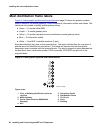
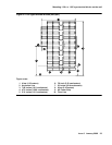
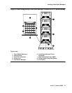
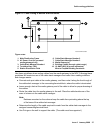
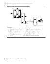
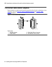
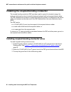
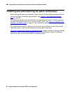
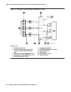
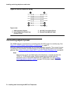
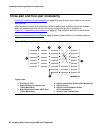
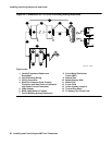
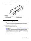
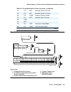
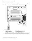
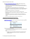
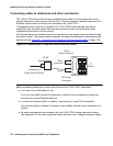
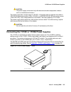
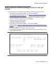
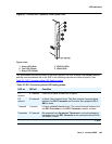
Connecting the C360 stackable switches
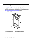
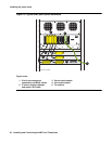
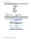
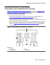
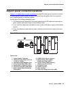
Powering up—AC input
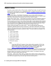
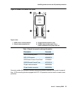
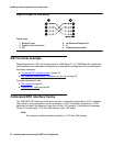
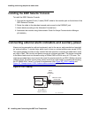
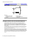
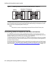
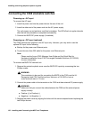
To connect the AC input:
1. Insert the power cord into the power inlet on the rear of the unit.
2. Insert the other end of the power cord into the AC power supply.
The unit powers up and performs a self-test procedure. The LEDs flash at regular intervals
after the self-test procedure is completed successfully.
3. Connect the BUPS DC power supply (if available).
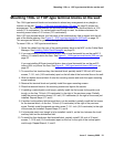
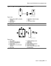
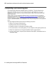
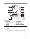
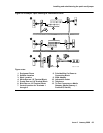
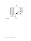
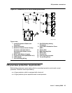
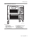
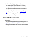
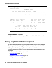
Powering up—DC input (optional)
The C360 switches can operate on the AC input only. However, you may wish to use the
optional DC input for the following:
● Backup for the power over Ethernet ports
● To provide more than 200 watts for the power over Ethernet ports
Note:
Note: Please see the Avaya C360 Manager User Guide and the Quick Start for
Hardware Installation Avaya C360 Converged Stackable Switches (03-300148)
for more information.
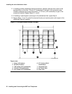
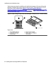
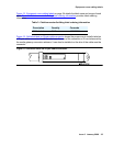
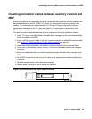
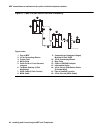
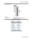
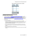
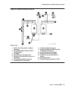
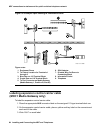
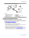
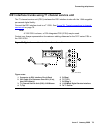
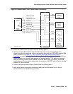
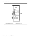
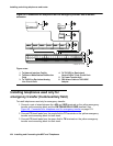
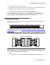
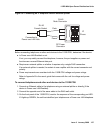
To connect the BUPS DC terminal unit:
1. Remove the protective plastic cover over the BUPS DC inputs by unscrewing the two
Phillips screws.
!
WARNING:
WARNING: The conductors to be used for connecting the BUPS to the C360 must be UL
Recognized and CSA Certified and be a minimum of 16 AWG or have a
cross-sectional area of 1.0 mm
2
.
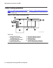
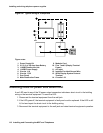
2. Connect the power cable to the terminals on the C360 and then external DC power supply.
!
WARNING:
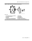
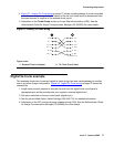
WARNING: Make sure that you connect the cables between the C360 and the external power
supply correctly.
● Positive (+) to Positive (+)
● Negative (-) to Negative (-)
3. Replace the plastic cover by aligning the holes with the screw receptacles and replacing the
two Phillips screws.