Installing and wiring telephone power supplies
112 Installing and Connecting the MDF and Telephones
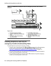
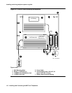
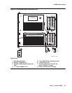
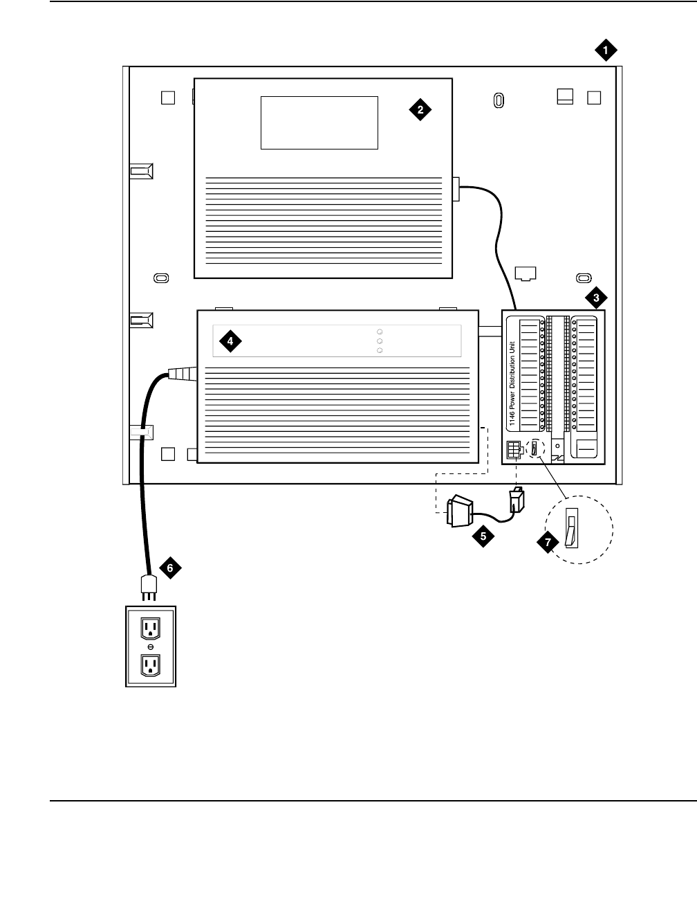
Figure 52: 1145B2/1146B2 mounting arrangement
Figure notes:
1. Wall Mounting Plate
2. Battery (1149B Shown)
3. 1146B2 Power Distribution Unit
4. 1145B2 Power Unit
5. Power Cable
6. Nonswitched Outlet (120 VAC, 20
amp or 230 VAC, 15 amp)
7. Battery Backup Switch Setting
1145 Power Unit
1149 Battery
OnBatteryReserve
Charging Battery
OutputPower On
1
2
3
4
5
6
7
8
9
10
11
12
13
14
15
16
17
18
19
20
21
22
23
24
25
26
27
28
29
30
31
32
-48V -48V
RTN RTN
Unit No.
Connected To:
1-8
1-32
0003_1 PDH 06259
6


