


808A Emergency Transfer Panel and telephone installation examples
Issue 3 January 2008 105
4. Connect ST leads on the yellow emergency transfer row/connecting block for each
emergency transfer telephone to the assigned terminal in the blue or white station
distribution field. The ST terminal leads should be terminated on the following pairs: 1, 4, 7,
10, 13, 16, 19, or 22 (the first pair of any 3-pair group).
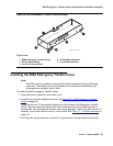
5. Install the telephone:
● Connect telephone to the information outlet.
● Install patch cords/jumper wires between the media gateway side and the station side of
the station distribution field on the MDF.
Installing telephones used for emergency
transfer and as normal extension (trunk/auxiliary field)
To install telephones used for emergency transfer and as a normal extension:
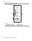
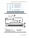
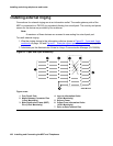
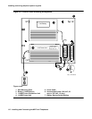
1. Connect a pair of wires between the -48V and GRD terminals on the yellow emergency
transfer row/connecting block to the EM TRANS RELAY PWR terminal. See
Figure 50: Connections for telephone used for emergency transfer and as normal
extension on page 104.
2. Connect CO trunk leads from the purple field to TC terminals on the yellow emergency
transfer row/connecting block for each trunk.
3. Connect CO trunk leads from the green field to TK terminals on the yellow emergency
transfer row/connecting block for each trunk.
4. Connect telephone leads from the purple analog line circuit pack row/ connecting block to
the LC terminals on the yellow emergency transfer row/connecting block for each
telephone.
5. Connect ST leads on the yellow emergency transfer row/connecting block for each
emergency transfer telephone to the assigned terminal in the blue or white station
distribution field.
6. Install the telephone:
● Connect telephone to the information outlet.
● Install patch cords/jumper wires between the media gateway side and the station.