


808A Emergency Transfer Panel and telephone installation examples
Issue 3 January 2008 103
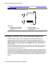
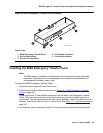
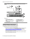
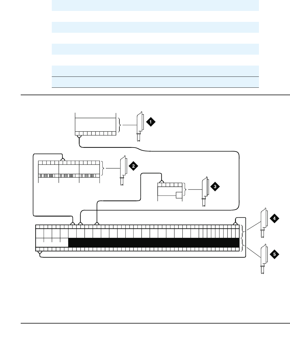
Figure 49: Connections for telephone used for emergency transfer
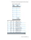
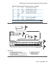
47 V-O NC2 Normally Closed 2 Contact
22 O-V NC1 Normally Closed 1 Contact
48 V-G COM2 Common 2 Relay Contact
23 G-V NO2 Normally Open 2 Contact
49 V-BR
24 BR-V
50 V-S GRD Ground from Aux Cable
25 S-V -48PX -48V from AUX Cable
Figure notes:
1. To Network Interface Circuitry
2. To TN747B (or Equivalent) Central Office
Trunk Circuit Pack
3. To Blue or White Station Distribution Field
4. To Power Transfer Unit
5. DB9 Alarm Cable to
TN2312BP Adapter
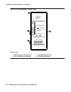
Table 18: Pin assignments for 25-pair connector (continued)
3 of 3
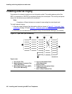
TC TK LC ST
XR 1m AL 1M 3M
ALARM MONITORS
3m 3w
TC TK LC ST TC TK LC ST TC TK LC ST TC TK LC ST
C
O
M
1
N
O
1
N
C
2
N
C
1
C
O
M
2
N
O
2
C
O
M
3
N
C
3
G
R
D
-48
V
123
2822
25
50
1
EMXR
2822
r758580b LAO 111104