


Auxiliary connector outputs (MCC1 and SCC1 Media Gateways only)
Issue 3 January 2008 81
Auxiliary connector outputs (MCC1 and SCC1
Media Gateways only)
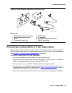
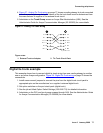
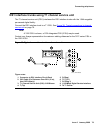
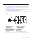
Connect a 25-pair cable from the AUX connector on the back of the expansion control carrier to
a connecting block on the trunk/auxiliary field.
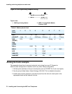
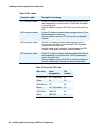
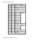
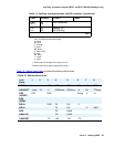
Table 11: Auxiliary lead appearances at AUX connector
on page 81 shows the:
● control carrier outputs cable pinouts
● pinouts for an external alarm
● port circuit pack and telephone pin designations
The control carrier AUX connector outputs include:
● Two inputs for external alarm signals
● Seven -48 VDC power sources for emergency transfer units
● Three -48 VDC power sources for remotely powering three attendant consoles or
telephone adjuncts
● A relay contact that actuates a customer-supplied light, bell, or similar device. The relay
can activate when a major, minor, or warning condition occurs. The device connected to
the alarm leads must not exceed a rating of 30Vac RMS or 60Vdc max, at 0.75A max. The
customer provided alarm circuit must also meet the requirements for an SELV (Safety
extra-low voltage) circuit; the alarm circuit power source must be a power supply or
transformer meeting the UL 60950 SELV, Level 3, or Level 5 requirements.
Table 11: Auxiliary lead appearances at AUX connector
Color
*
Pinouts Output Power
W-BL
BL-W
26
1
Major
†
W-O
O-W
27
2
Minor
†
W-G
G-W
28
3GRD
W-BR
BR-W
29
4GRD
W-S
S-W
30
5GRD
R-BL
BL-R
31
6GRD
1 of 3