


LED indicators
Issue 3 January 2008 149
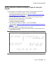
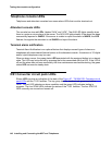
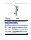
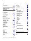
Figure 67: TN1654 DS1 Converter circuit pack LEDs
The yellow LED indicates the state of the fiber interface, the fiber channel, the control channel,
and the communications link to the SPE in the following manner and order of priority. See
Table 23: DS1 Converter yellow LED flashing states
.
.
Figure notes:
1. Alarm LED (Red)
2. Test LED (Green)
3. Busy LED (Yellow)
4. STATUS LEDs
5. SPAN LEDs
Table 23: DS1 Converter yellow LED flashing states
LED on LED off Condition
0.1
second
0.1 second Fiber out-of-frame or fiber loss of signal.
0.5
second
0.5 second In frame, fiber channel down. The fiber channel communicating
between the DS1 Converter and the other fiber endpoint (EI or
SNI) is down.
1 second 1 second In frame, control channel down. The control channel between the
two DS1 Converters in the DS1 Converter complex is down.
2 seconds 0.2 second No response from the server. The server is not acknowledging
messages from the DS1 Converter or the communications link to
the server is down.
1 of 2