Installing and wiring telephone power supplies
116 Installing and Connecting the MDF and Telephones
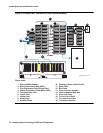
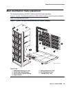
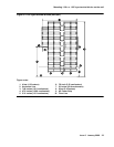
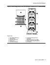
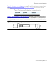
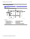
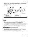
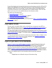
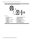
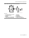
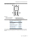
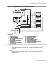
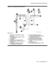
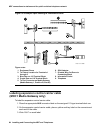
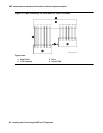
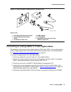
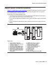
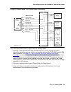
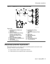
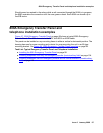
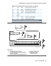
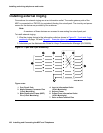
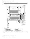
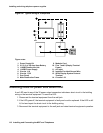
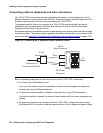
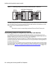
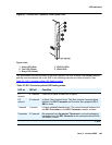
See Figure 53: Expanded power distribution unit on page 113 while installing the power
distribution unit. To install the expanded power distribution unit:
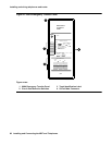
1. Set the spacer bracket onto the mounting plate and secure with the #8-32 x 1/2-inch
shoulder screws. The spacer bracket is not shown in the figure but is installed behind the
top power distribution unit.
2. Slide the keyhole slots in the power distribution unit over the shoulder screws.
3. Insert the #8-32 x 1-inch screw through the distribution unit, through the spacer bracket, and
into the plate. The mounting hole is located just above the wire clip. Tighten the screw
securely.
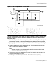
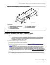
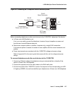
4. Set the battery back-up switch to the 1-32 (down) position.
5. Power-down the 1145B2 unit as described on the label on the side of the unit.
6. Remove the output power cable between the 1145B2 and the 1146B2 units. The cable will
not be reused.
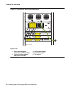
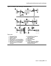
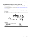
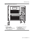
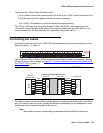
7. Connect the P1 connector end of the “T” cable to the bottom power distribution unit.
Connect the P2 connector to the top distribution unit. Connect the P3 connector to the
1145B2.
8. Power-up the 1145B2 as described on the label on the side of the unit.
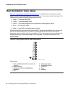
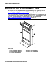
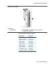
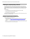
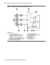
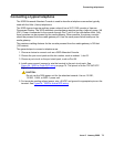
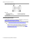
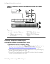
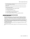
Powering up and testing the power supply
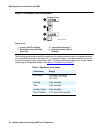
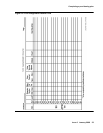
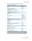
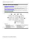
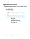
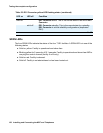
Table 20: Power supply LEDs on page 116 describes the meaning of the power supply LEDs
when lit.
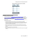
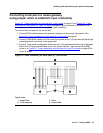
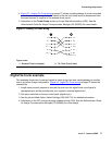
To power up and test the power supply:
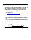
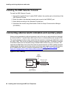
1. Connect the AC power cord to the power supply and route the cord to an appropriate AC
outlet using the clips provided on the unit.
Note:
Note: A maximum of four power supplies can be powered from one dedicated 100–120
V, 50/60 Hz, 20-amp feeder or 200–240 V, 50/60 Hz, 10-amp feeder. Use only
nonswitched outlets.
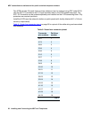
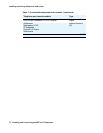
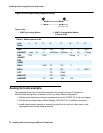
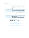
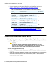
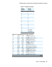
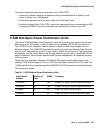
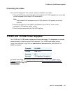
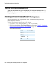
Table 20: Power supply LEDs
LED
color
Meaning
Green Power Supply is providing power
Yellow Battery is charging
Red Power Supply is on battery reserve