


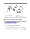
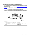

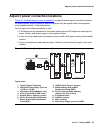
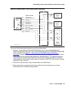
Auxiliary connector outputs (MCC1 and SCC1 Media Gateways only)
Issue 3 January 2008 83
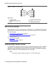
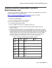
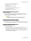
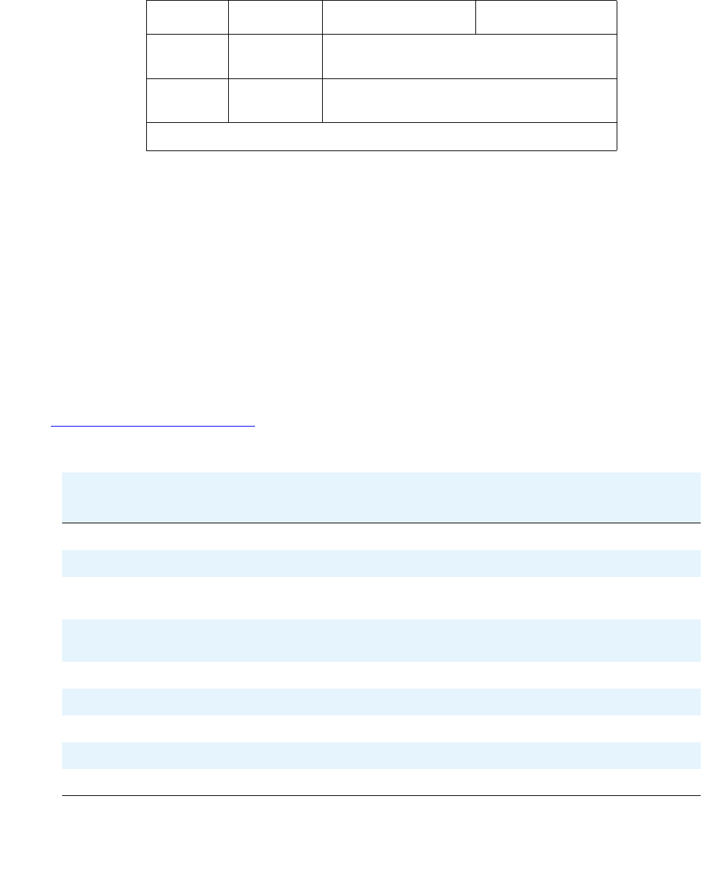
Table 12: Station pinout chart provides the station printout chart.
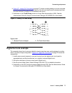
V-BR
BR-V
49
24
Not Connected
V-S
S-V
50
25
INADS Tip
INADS Ring
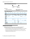
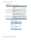
*. Color designation is the main wire color and the color of the stripe on the
wire. The following wire colors apply:
W White
BL Blue
O Orange
G Green
BR Brown
S Slate (Grey)
R Red
BK Black
Y Yellow
V Violet
†. External alarm with signal incoming to server.
3External alarm with signal outgoing from server.
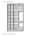
Table 12: Station pinout chart
Jack
Name
1 2 3 4 5 6 7 8
BRI-T +TX +RX -RX -TX -V GND
ADJUNCT +Vadj T0 -V GNDVoice RRVoice +V S0 TTVoice
DSS
(QUEST)
DTX DRX OKdig -V +V
DSS
(ISDN)
BRI-A GND TX RX -V
BRI-U TX RX -V GND
DCP TIP RING
ANALOG TIP RING
HANDSET -TX +RX -RX +TX
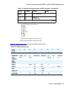
Table 11: Auxiliary lead appearances at AUX connector (continued)
Color
*
Pinouts Output Power
3 of 3