


Installing connector cables between auxiliary cabinet and MDF
Issue 3 January 2008 39
Installing connector cables between auxiliary cabinet and
MDF
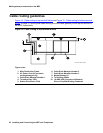
Auxiliary equipment that connects to the MDF can be mounted inside the auxiliary cabinet. The
equipment connects to an ED-1E1443-10 (Group 1) intraconnection panel mounted in the
cabinet. This intraconnection panel consists of a 110-type 100-pair wiring block. Auxiliary
equipment is connected to the 110-type wiring block. The wiring block is pre-wired to four
25-pair female connectors mounted on the outside rear of the cabinet.
To install connector cables between the auxiliary cabinet and the main distribution frame:
1. Install “D” rings on the wall between the cable slack manager and the terminal/connecting
blocks mounted on the MDF.
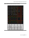
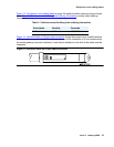
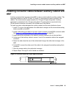
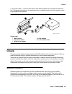
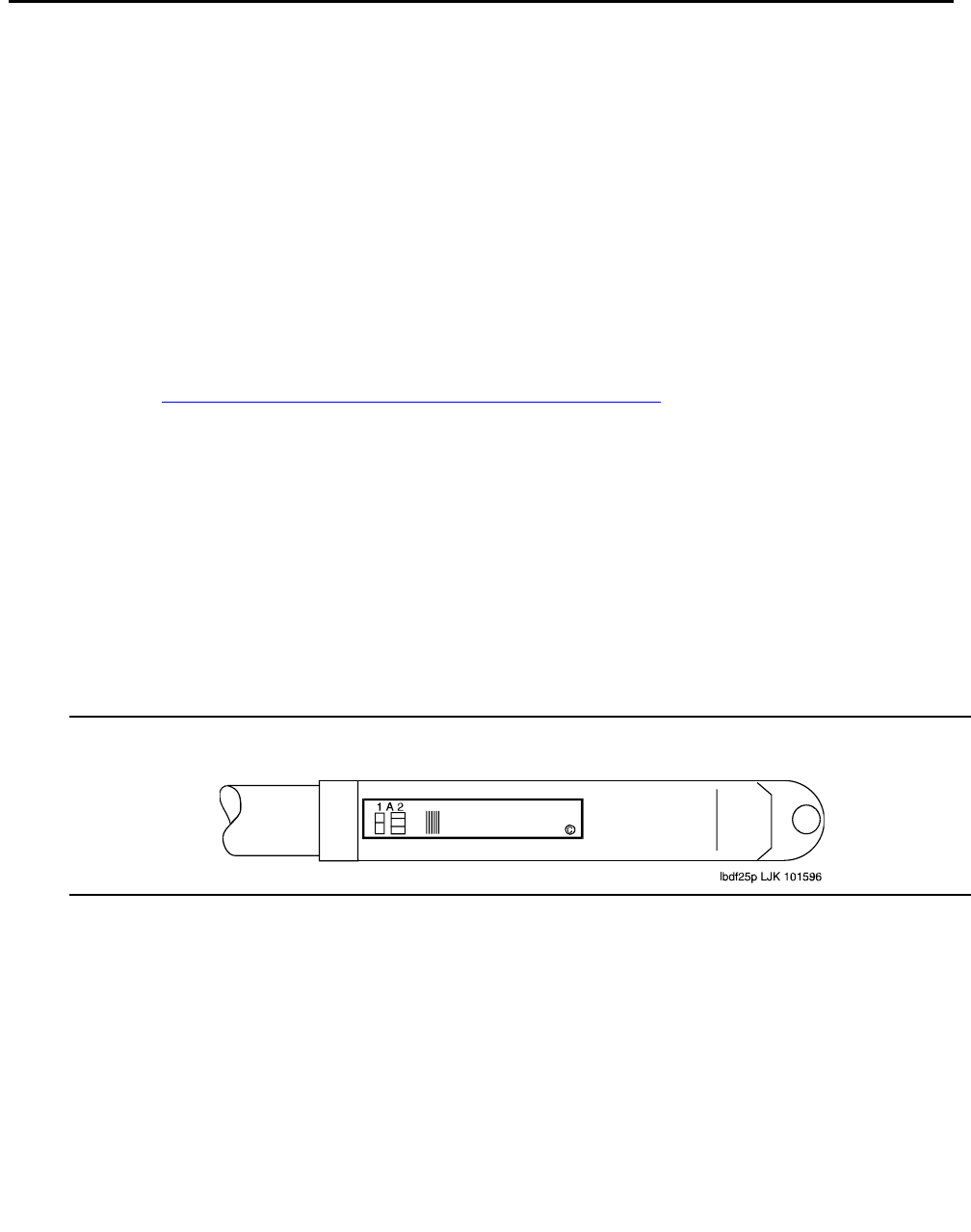
2. Install a self-sticking port label on the rear of each connector on the B25A connector cable.
See Figure 16: Self-stick label on 25-pair cable connector
on page 39.
3. Labels should be positioned so the cabinet connector retainers do not obscure them.
4. At the rear of the auxiliary cabinet, connect 1 end of the connector cable to the assigned
connector.
5. Route the cable down the rear of the cabinet and through the cable slack manager to the
MDF.
6. At the MDF, connect the other end of the cable to the assigned terminal/connecting block
connector.
7. Store the excess cable in the cable slack manager.
8. Repeat Steps 2 through 6 until all cables are installed.
Figure 16: Self-stick label on 25-pair cable connector