Cable routing guidelines
Issue 3 January 2008 37
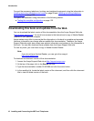
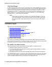
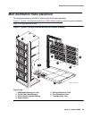
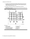
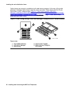
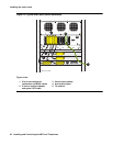
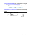
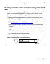
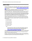
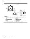
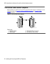
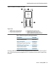
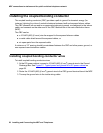
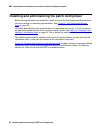
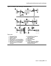
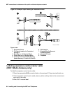
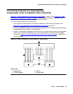
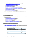
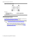
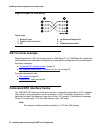
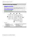
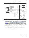
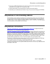
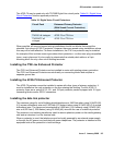
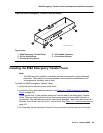
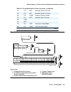
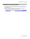
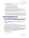
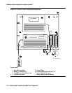
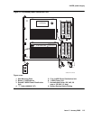
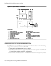
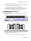
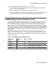
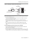
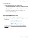
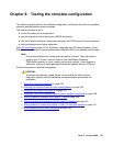
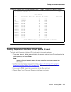
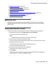
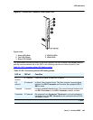
Figure 15: Cable routing to bottom terminal blocks
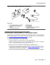
Use these guidelines when routing cables from the media gateway to the MDF. Following these
guidelines will maximize use of the cable slack managers and make future cabling additions
and changes easier.
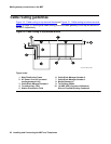
● Connect each port cable at the media gateway, and then route it along the front trough of
the cable slack manager to the connecting/terminal block, where the cable is terminated.
● Leave enough slack at the media gateway end of the cable to allow for proper dressing of
the cables.
● Route the cable from the media gateway to the wall. Place the cable beside one of the
rows of columns in the cable slack manager.
Note:
Note: Retainers mounted on the columns keep the cable from protruding above the top
of the base of the cable slack manager.
● Determine the length of the cable required to reach from the cable slack manager to the
assigned connecting/terminal block.
● Use D rings on the wall to support the cable. (The cable must be supported.)
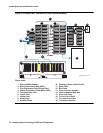
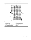
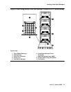
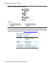
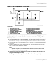
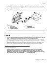
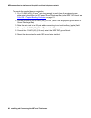
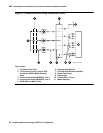
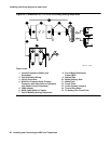
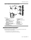
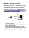
Figure notes:
1. Main Distribution Frame
2. AC Power Cord (AC-powered
media gateways only)
3. Cable Slack Manager Number 1
4. Trunk/Auxiliary Field
5. Station Distribution Field
6. Cable Slack Manager Number 2
7. Cable Slack Manager Number 3
8. Media Gateway(s)
9. Building Cables (through cable trough)
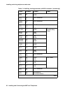
10. 10 AWG (#25) (6 square millimeters)
Wire to Coupled Bonding Conductor
r758432b MMR 052996