


Installing and wiring telephones and trunks
88 Installing and Connecting the MDF and Telephones
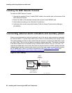
Installing the 26B1 Selector Console
To install the 26B1 Selector Console:
1. Connect the supplied 3-foot (1 meter) D8AC cable to the modular jack on the bottom of the
26B1 Selector Console.
2. Route the cable to the attendant console and connect to the DXS/BLF jack.
3. Attach labels according to the Attendant Console form.
4. Administer the console using Administrator Guide for Avaya Communication Manager
(03-300509).
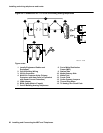
Connecting external alarm indicators and auxiliary power
Alarms can be generated on adjunct equipment, sent to the server, and recorded and reported
as “external alarms.” A typical major alarm input is from an uninterruptible power supply (UPS).
The media gateway provides a relay contact that can operate a customer-provided alarm, such
as a light or bell. The circuitry and power source are customer-provided. The device connected
to the alarm leads must not exceed a rating of 30Vac RMS or 60Vdc max, at 0.75A max. The
customer provided alarm circuit must also meet the requirements for an SELV (Safety extra-low
voltage) circuit; the alarm circuit power source must be a power supply or transformer meeting
the UL 60950 SELV, Level 3, or Level 5 requirements. See Figure 42: IPSI-2 cabling
and
Figure 43: Sample Issue 1 IPSI-2 alarm cable connectivity
on page 89.
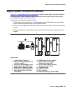
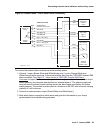
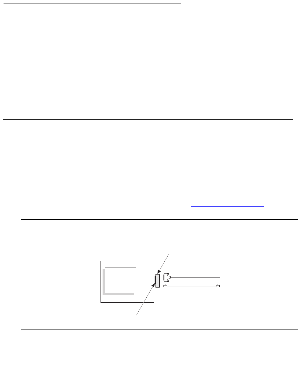
Figure 42: IPSI-2 cabling
IPSI-2
TN2312BP
Carrier
Carrier
I/O
cable
IPSI-2
adapter
700 263 502
DB9 alarm cable
700 276 389
RJ45 CAT5 cable
IP connection
dli 1 KLC 111104
Amphenol/RJ21
25 pair connector